120
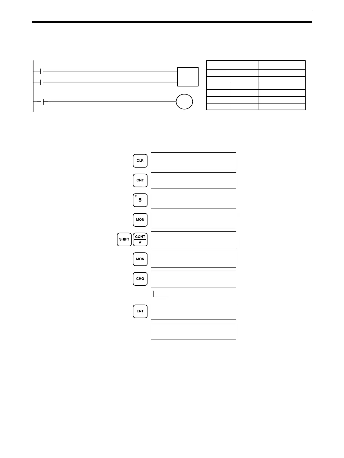
The following example shows how either bits or counters can be controlled
with the Force Set/Reset operation. The displays shown below are for the
following program section.
000 LD 0000
001 LD 0200
002 CNT 05
# 0100
003 LD CNT 05
004 OUT 0101
0000
CNT05
0101
0200
CP
R
CNT 05
#0100
Address Instruction Operands
The following displays show what happens when CNT 05 is set when
bit 0000 is ON.
(This example is in RUN mode.)
Indicates that force set/reset is in progress.
0Ć000
0Ć000
CNT 00
0Ć000
CNT 05
0 C 05
0100
0 0000 C 05
0100
0 0000 C 05
^OFF 0100
0 0000 C 05
~ ^OFF 0100
0 0000 C 05
^ ON 0099
0 0000 C 05
^OFF 0099
After one scan the value
of 0000 is reset to 0.
4-1-3 Hexadecimal/BCD Data Modification
When the Bit/Multibit Monitor operation is being performed and a BCD or
hexadecimal value is leftmost on the display, CHG can be input to change
the value. Dedicated words cannot be changed.
If a timer or counter is leftmost on the display, the PV will be displayed and
will be the value changed. PV can be changed in RUN mode only when the
timer or counter is operating.
To change contents of the leftmost word address, press CHG, input the de-
sired value, and press ENT.
Example
Monitoring Operation and Modifying Data Section 4-1
 Loading...