31
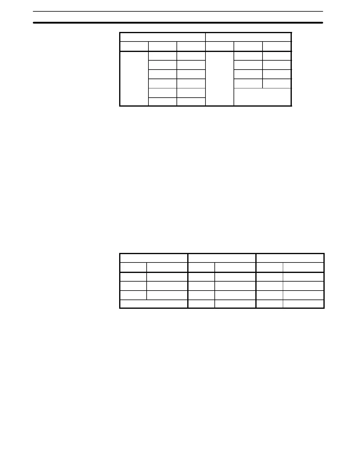
Inputs Outputs
Word Bit Terminal Word Bit Terminal
00 0000 0 01 0100 0
0001 1 0101 1
0002 2 0102 2
0003 3 0103 3
0004 4 ---
0005 5
After the program is executed, the status of outputs determined by the pro-
gram is actually output from the output bits to the output terminals. Also, the
current status of all inputs is read from the input terminals to the input bits.
Note Do not use normally closed input signals for SP-series PCs with DC power
supplies. Doing so can cause counters and shift registers to reset and bits
programmed with the KEEP instruction to invert when power is interrupted,
resulting in errors in program execution.
3-2-3 Work Bits
Work words and bits can be used in programming as required to control oth-
er bits. The work bits listed in the following table well as bits in the DR and
LR areas can be used as work bits if they are not used for other purposes.
The actual application of work bits is described in 3-6-6 Work Bits (Internal
Relays). In the SP10, bits 0006 and 0007 cannot be used for work bits or for
any other purpose.
SP10 SP16 SP20
Word Bits Word Bits Word Bits
00 0008 to 0015 00 0010 to 0015 00 0012 to 0015
01 0104 to 0115 01 0106 to 0115 01 0108 to 0115
02 0200 to 0215 02 0200 to 0215 02 0200 to 0215
--- 10 to 20 1000 to 2015 10 to 20 1000 to 2015
3-2-4 Dedicated Bits
The dedicated bit area contains flags and control bits used for monitoring
system operation, accessing clock pulses, and signalling errors. In the SP10,
word addresses range from 03 through 04; bit addresses, from 0300 through
0411. In the SP16 and SP20, word addresses range from 03 through 09; bit
addresses, from 0300 through 0915. Bits in the dedicated bit area that are
not assigned functions cannot be used for work bits or for any other purpose.
The following table lists the functions of flags and control bits in the dedicated
bit area. Most of these bits are described in more detail following the table.
Unless otherwise stated, flags are OFF until the specified condition arises,
when they are turned ON. Bits 0311 through 0315 are turned OFF when the
END is executed at the end of each program scan, and thus cannot be moni-
tored on the Programming Console. Other bits are OFF until set by the user.
Memory Areas Section 3-2
 Loading...