40
Basic Ladder Diagram A ladder diagram consists of one line running down the left side with lines
branching off to the right. The line on the left is called the bus bar; the
branching lines, instruction lines or rungs. (Sometimes a right bus bar is also
drawn.) Along the instruction lines are placed conditions that lead to other
instructions on the right side. The logical combinations of these conditions on
the ladder determine when and how the right-hand instructions are executed.
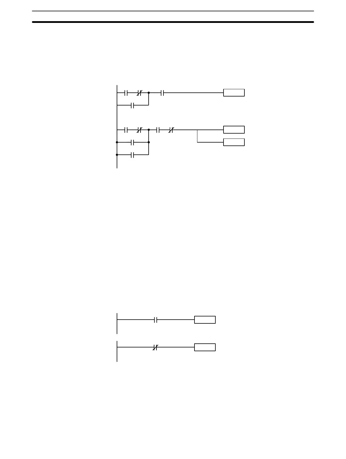
A simple ladder diagram is shown below.
0000 0001
Instruction
Instruction
0002
0312
0010 0002
0011
0012
0003 DR 0050
Instruction
As shown in the diagram above, instruction lines can branch apart and they
can join back together. The vertical pairs of lines are called conditions. Con-
ditions without diagonal lines through them are called normally open condi-
tions and correspond to a LOAD, AND, or OR instruction. The conditions with
diagonal lines through them are called normally closed conditions and corre-
spond to a LOAD NOT, AND NOT, or OR NOT instruction. The number
above each condition indicates the operand bit for the condition. It is the sta-
tus of the bit associated with each condition that determines the execution
condition for following instructions. The way the operation of each of the in-
structions corresponds to a condition is described below. Before we consider
these, however, there are some basic terms that must be explained.
Each condition in a ladder diagram is either ON or OFF depending on the
status of the operand bit that has been assigned to it. A normally open condi-
tion is ON if the operand bit is ON; OFF if the operand bit is OFF. A normally
closed condition is ON if the operand bit is OFF; OFF if the operand bit is
ON. Generally speaking, you use a normally open condition when you want
something to happen when a bit is ON, and a normally closed condition when
you want something to happen when a bit is OFF.
Instruction
Instruction
0000
0000
Instruction is executed
when bit 0000 is ON.
Instruction is executed
when bit 0000 is OFF.
Normally open
condition
Normally closed
condition
In ladder diagram programming, the logical combination of ON and OFF con-
ditions before an instruction determines the compound condition under which
the instruction is executed. This condition, which is either ON or OFF, is
called the execution condition for the instruction. All instructions other than
LOAD instructions have execution conditions.
The operands designated for any of the ladder instructions can be any I/O,
work, DR, or dedicated bit. This means that the conditions in a ladder dia-
Normally Open and
Normally Closed
Conditions
Execution Conditions
Operand Bits
Basic Programming Section 3-4
 Loading...