8 - 3
8 Serial Line Monitor
NX-series Communications Interface Units User’s Manual (W540)
8-1 How the Serial Line Monitor Works
8
8-1-2 CIF Serial Line Monitor Tab Page
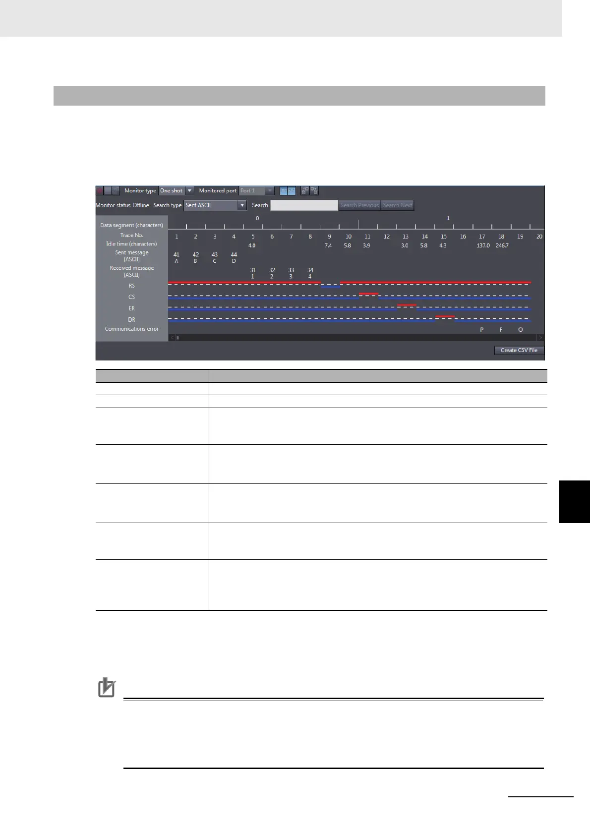
On the Support Software, the monitor data is displayed in the CIF Serial Line Monitor tab page. The
configuration of the CIF Serial Line Monitor Tab Page in the Sysmac Studio is shown below. The data
values are shown from left to right along a time scale. The left edge is the starting point of the monitor.
For Support Software other than the Sysmac Studio, refer to the operation manual for the Support Soft-
ware that you are using.
Precautions for Correct Use
The control signals are recorded from when one character of a message is sent or received.
Therefore, changes in the control signals are not shown in the CIF Serial Line Monitor tab page
even when they change unless a message is sent or received. Also, changes in the control sig
-
nals may not be shown in the CIF Serial Line Monitor tab page if the signals change for periods
sho
rter than the time to send or receive one character.
8-1-2 CIF Serial Line Monitor Tab Page
Display item Description
Data segment (characters) A serial number is given for each segment of 10 trace numbers.
Trace No. Trace numbers are assigned to sent or received messages by character.
Idle time (characters) The idle time is the number of characters between two sent or received messages
when
nothing is sent or received for more than the time required for two characters.
The maximum value is 6,553.5 characters.
Sent message (ASCII) The top row gives the sent messages in hexadecimal.
The bottom row gives the sent messages in ASCII char
acters. Perio
ds are displayed
when the actual characters cannot be displayed, such as for control characters.
*1
*1. You can show or hide the characters with the
Display the characters
button in the CIF Serial Line Monitor tab page.
Received message
(ASCII)
The top row gives the received messages in hexadecimal.
The bottom row gives the received messages in ASCII characters. Periods are displayed
when the actual characters cannot be displayed, such as for control characters.
*1
RS, CS, ER, and DR
*2
*2. You can show or hide the signals with the Display the details button in the CIF Serial Line Monitor tab page.
The ON/OFF values of the RS, CS, ER, and DR control signals are displayed.
ON: A red line is displayed above the base line.
OFF: A blue line is displayed below the base line.
Communications error
*2
Abbreviations are displayed for communications errors that occur.
*3
P: Parity error
F: Framing error
O: Overrun error
*3. If more than one type of communications error occur at the same time, the p
r
iority of the error display from the
highest priority is as follows: parity error, framing error, and overrun error.
 Loading...