4 Installation and Wiring
4 - 20
NX-series Communications Interface Units User’s Manual (W540)
4-4 Wiring Communications
This section describes how to wire a CIF Unit to perform communications with an external serial com-
munications device.
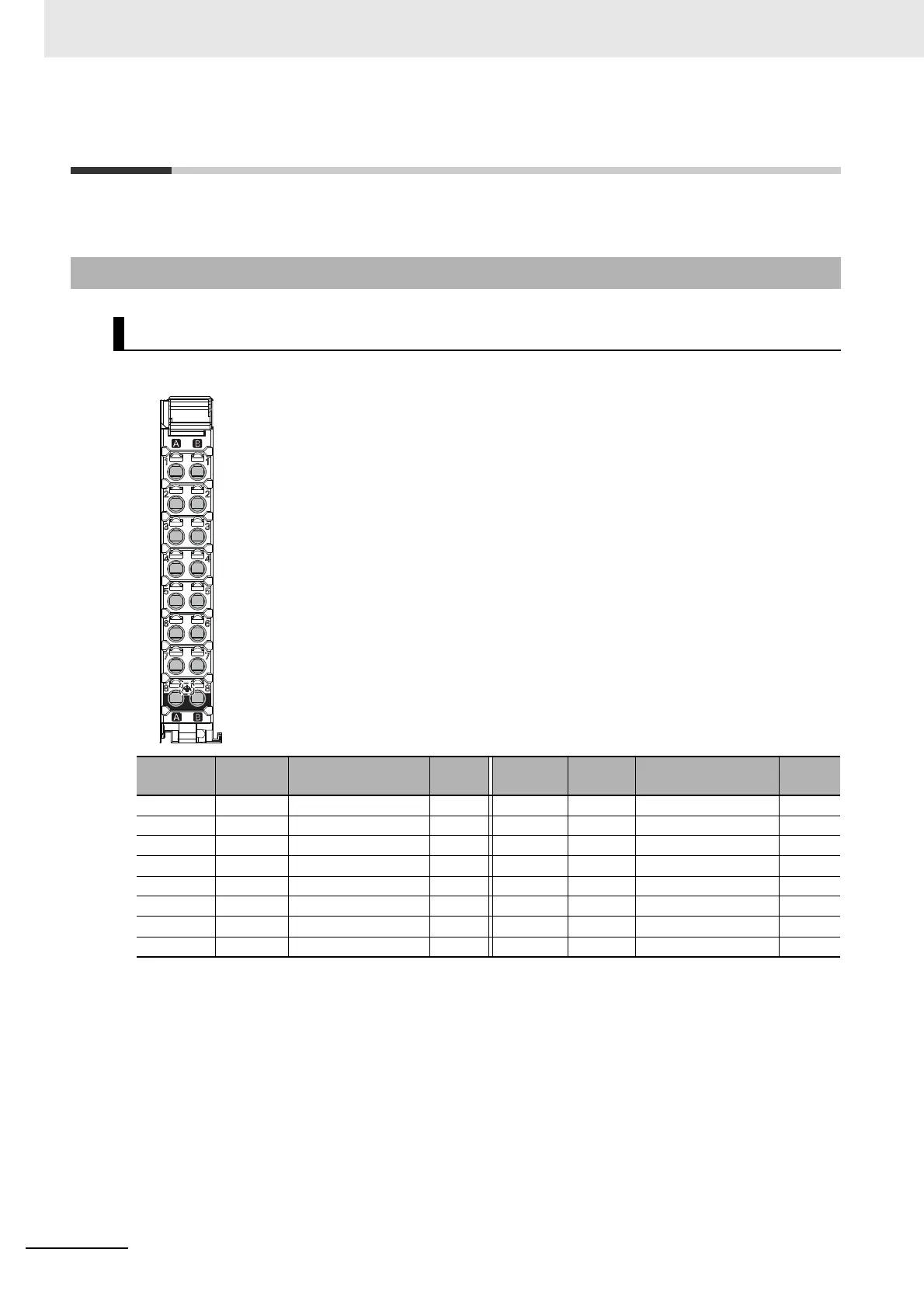
The terminal arrangement of the NX-CIF101 is given below.
4-4-1 Terminal Arrangement
NX-CIF101 Terminal Arrangement
Terminal
No.
Abbrev. Signal name I/O
Terminal
No.
Abbrev. Signal name I/O
A1 SD Send data Output B1 RD Receive data Input
A2 RS Request to send Output B2 CS Clear to send Input
A3 ER Data terminal ready Input B3 DR Data set ready Output
A4 SG Signal ground -- B4 SG Signal ground ---
A5 NC Not used. -- B5 NC Not used. ---
A6 SHLD Shield -- B6 SHLD Shield ---
A7 NC Not used. -- B7 NC Not used. ---
A8 FG Frame ground -- B8 FG Frame ground ---
A1
A2
A3
A4
A5
A6
A7
A8
B1
B2
B3
B4
B5
B6
B7
B8
 Loading...