A - 25
Appendices
NX-series Communications Interface Units User’s Manual (W540)
A-3 List of NX Objects
A
A-3-3 NX Objects for the NX-CIF210
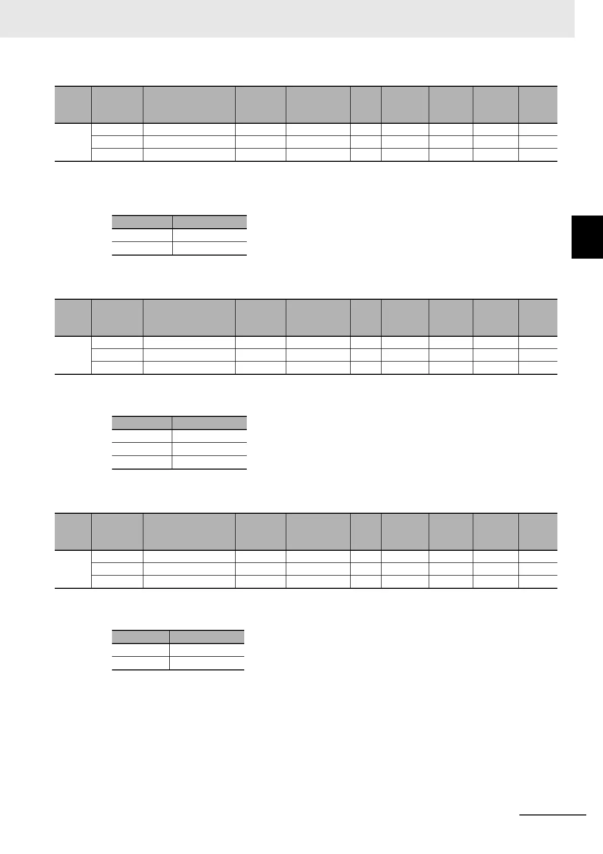
• The following table gives the meanings of the set values for the Ch1 Data Bit Length and Ch2 Data
Bit Length.
• The following table gives the meanings of the set
valu
es for the Ch1 Parity and Ch2 Parity.
• The following table gives the meanings of the set values
for the Ch1 Stop Bits and Ch2 Stop Bits.
Index
(hex)
Subindex
(hex)
Object name Default Data range Unit
Data
type
Access
I/O allo-
cation
Data
attri-
bute
5003 --- Data Bit Length --- --- --- --- --- --- ---
01 Ch1 Data Bit Length 0 0 or 1 --- USINT RW No Y
02 Ch2 Data Bit Length 0 0 or 1 --- USINT RW No Y
Set value Description
0 7 bits
1 8 bits
Index
(hex)
Subindex
(hex)
Object name Default Data range Unit
Data
type
Access
I/O allo-
cation
Data
attri-
bute
5004 --- Parity --- --- --- --- --- --- ---
01 Ch1 Parity 1 0 to 2 --- USINT RW No Y
02 Ch2 Parity 1 0 to 2 --- USINT RW No Y
Set value Description
0 None
1 Even
2 Odd
Index
(hex)
Subindex
(hex)
Object name Default Data range Unit
Data
type
Access
I/O allo-
cation
Data
attri-
bute
5005 --- Stop Bits --- --- --- --- --- --- ---
01 Ch1 Stop Bits 0 0 or 1 --- USINT RW No Y
02 Ch2 Stop Bits 0 0 or 1 --- USINT RW No Y
Set value Description
0 2 bits
1 1 bit
 Loading...