14
SECTION 1
Part Names and Functions
RFID System
User’s Manual
SECTION 1
Product Overview
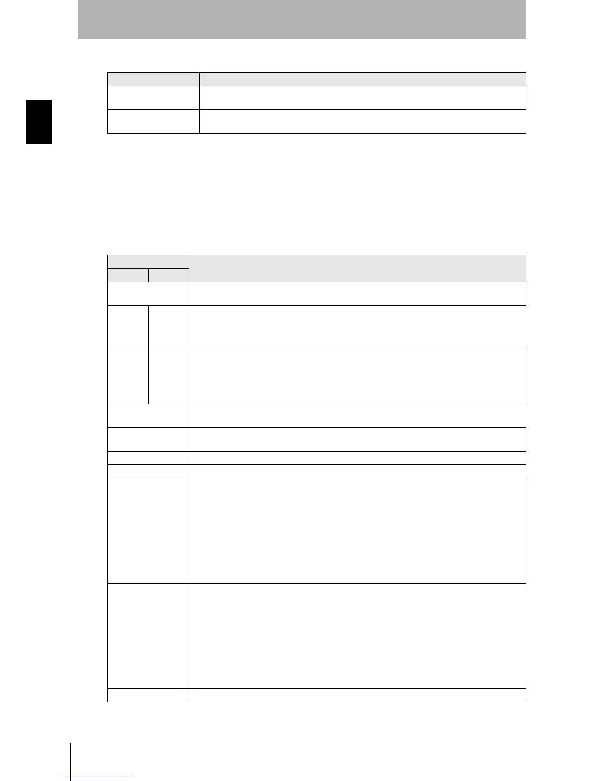
Power Supply and Ground Terminals
External I/O Port
The external I/O port is used to connect external I/O signals.
There are two external I/O signal arrangements that can be used for the same port: the same signal
arrangement as the V600-CA5D@@ and a signal arrangement unique to the V680-CA5D@@-V2.
The desired I/O signal arrangement can be specified using the PARAMETER SET (SP) command. In
Self-execution Mode, the use of ports other than RUN and RST can be set.
Description Description
Power supply terminals Supply 24 VDC power to these terminals.
Recommended power supply: OMRON S8VS-03024.
Ground terminal The ground terminal. Connect this terminal to an independent ground line connected to 100
Ω. or
less.
Description
Description
V600 I/O V680 I/O
RUN Turns ON when the ID Controller is operating normally and the communications are possible with the
host device.
BUSY OUT3 BUSY: Output from when a tag communications command is received from the host device until tag
communications have been completed. This is the default setting.
OUT3: User output 3. This output can be controlled with the CONTROLLER CONTROL (CC) com-
mand.
ERROR OUT4 ERROR: Output for 500 ms when a tag communications error, host communications error, or hard-
ware error has occurred. The output time can be changed with the PARAMETER SET (SP)
command. This is the default setting.
OUT4: User output 4. This output can be controlled with the CONTROLLER CONTROL (CC) com-
mand.
OUT1 OUT1: User output 1. This output can be controlled with the CONTROLLER CONTROL (CC) com-
mand.
OUT2 OUT2: User output 2. This output can be controlled with the CONTROLLER CONTROL (CC) com-
mand.
COM_O Common terminal for outputs.
RST External reset input for emergency stops. The ID Controller is reset when an input is received.
TRG1 V680 Command System
If a trigger communications designation (SI, RI, or PI) is specified, the command received by Antenna
1 will be executed on the rising edge of the TRG1 input. If any other communications designation is
specified, TRG1 is used as user input 1, which can be read using the CONTROLLER CONTROL
(CC) command.
V600 Command System
If pin 6 on DIP switch SW4 (Lower Trigger Execution Setting) is turned ON, any command already
received by Antenna 1 will be executed on the rising edge of the TRG1 Input. If pin 6 is turned OFF,
TRG1 is used as user input 1, which can be read using the CONTROLLER CONTROL (CC) com-
mand.
TRG2 V680 Command System
If a trigger communications designation (SI, RI, or PI) is specified, the command received by Antenna
2 will be executed on the rising edge of the TRG2 input. If any other communications designation is
specified, TRG2 is used as user input 2, which can be read using the CONTROLLER CONTROL
(CC) command.
V600 Command System
If pin 6 on DIP switch SW4 (Lower Trigger Execution Setting) is turned ON, any command already
received by Antenna 2 will be executed on the rising edge of the TRG2 input. If pin 6 is turned OFF,
TRG2 is used as user input 2, which can be read using the CONTROLLER CONTROL (CC) com-
mand.
COM_I Common terminal for inputs

 Loading...


