30
SECTION 2
Connection and Wiring
RFID System
User’s Manual
SECTION 2
Installation, Connections, and Wiring
Connection and Wiring
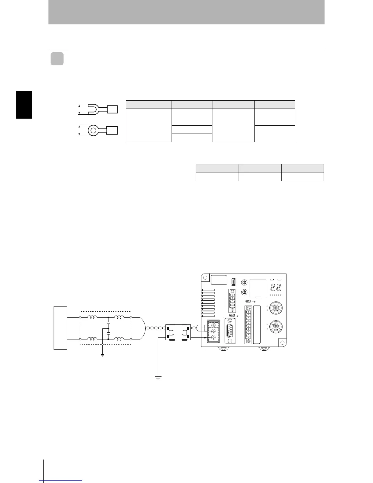
Power Supply and Ground Wires
The power supply and ground terminals use M3 self-rising screws. The following type of crimp termi-
nals can be connected to these terminals.
Recommended tightening torque: 0.5 N·m
Examples of Applicable Crimp Terminals
Manufacturer Model Applicable wire Typ e
J.S.T. Mfg. Co., Ltd.
1.25-N3A
0.25 to 1.65 mm
2
AWG22 to AWG16
Forked
V1.25-N3A
1.25-MS3
Round
V1.25-MS3
6.4 max.
6.4 max.
(
For M3 screw)
• Provide 24 VDC to the Controller. The allowable fluctu-
ation in the power supply is 24 VDC (
−15%/+10%).
● Recommended Compact DC Power Supply (OMRON)
Model Output capacity Input voltage
S8VS-03024 24 VDC, 1.3 A 100 to 240 VAC
• ID Controllers have built-in noise countermeasures
against noise superimposed on the power supply line.
Ground noise can be reduced further by attaching a fil-
ter to the power supply line.
Note: The maximum power consumption of the Controller is
30 W (1.3 A at 24 VDC). The inrush current, however,
must be considered when selecting the power supply
capacity. A power supply with an output of 1.3 A min. at
24 VDC is recommended.
• Twisted-pair wire is recommended for the power line.
• To increase resistance to noise, ground to 100
Ω or
less to an independent ground pole.
• Use a class 2 power supply.
+ 24 V
0 V
Line filter
Ground to a resistance of 100
Ω or less
Ferrite core
DC power supply

 Loading...


