EN-7
4-2
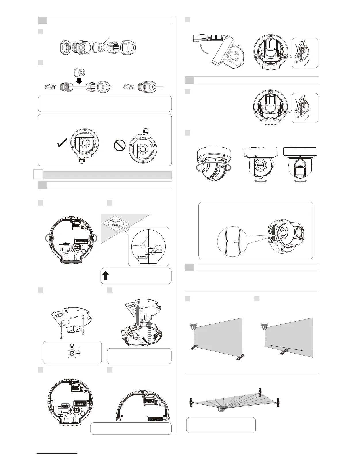
ANGLE ADJUSTMENT
4-3
LASER AREA CONFIRMATION
It is recommended that the optional Laser Area Checker(LAC-1) is used to
confirm the location of the laser plane.
Check that the laser beams are targeted to the desired areas.
Tips: Two units of LAC-1 (option) can make it easier to confirm
the detection area.
1
Slightly loosen 3 fixing screws.
2
Use the laser area checker to adjust the angle and then tighten
3 fixing screws.
7
Insert the base hook in to the base cover and ensure that the fixing screw
does not jam against the cover.
Close the base cover, and then tighten the 3 screws to fix it.
-Vertical Detection Area
-Horizontal Detection Area
1
Adjust the detector's angle so that
the laser beam hits the farthest
position of the required area and
just the bottom of the detector.
2
Check that the entire area is
covered properly with laser area
checker (option: LAC-1).
Note >>
For detailed instructions refer to the
LAC-1 instruction manual.
Note >>
Align the markings of the base unit and main unit to be the guideline
for the direction of the detection area.
1.
2.
3.
Approx. 4° virtically and horizontally
4
INSTALLATION AND ANGLE ADJUSTMENT
4-1
WALL OR CEILING MOUNTED
Caution >>
Do not supply the power for this unit during wiring.
1
Remove the mounting bracket
from the base, using a tool such
as flathead screwdriver.
Methods for ceiling mounting and wall mounting are the same.
2
Place the supplied paper template
on the mounting surface and open
2 mounting holes.
3
Mount the mounting bracket to the
mounting surface.
Screws to fix the mounting bracket
are not included.
4
Attach the base into the mounting
bracket until it clicks.
5
Perform wiring. (See 5-1.)
6
Connect the base and main unit
with wiring. When the LED at the
side of the relay connecter is ON,
turn OFF the power supply before
connecting them.
Relay connector
Caution >>
The LAN cable with the cover on cannot passes through the cable gland.
Be sure to remove the cover before use.
Caution >>
Do not install the cable gland upward than horizontal line. Doing so may reduce the
waterproof performance.
3-6
INSTALLING NETWORK CABLE
1
Disassemble the cable gland.
2
Pass the Ethernet plug with the correct order and direction. Put the seal from
the side.
Seal
Sensor side
±180°horizontally
Note >>
Pull the base to make sure that the
base is completely attached.
Note >>
Make sure that the arrow points upward
when mounting the detector on the wall.
180° 180°
Note >>
3.5 mm max.
Φ9.5 mm max.
4 mm
/ No.8

 Loading...