EN-8
5-2
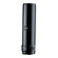
PROGRAMMABLE SIGNAL OUTPUT
5-3
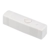
PROGRAMMABLE SIGNAL INPUT (RLS-2020S only)
The three output terminals can be configured as NO/NC. They
are however fixed as open when the unit is not energized.
The outputs are programmable from options below.
Alarms
• Master alarm (MO)
• Zone alarm
(A1, A2, B1, B2)
Troubles
• Anti-masking (AM)
• Anti-rotation (AR)
• Soiling (SO)
• Environmental disqualification
(DQ)
• Device trouble (TR)
• Tamper output (TA)
5
PARTS LAYOUT INSIDE AND THEIR FUNCTIONS
5-1
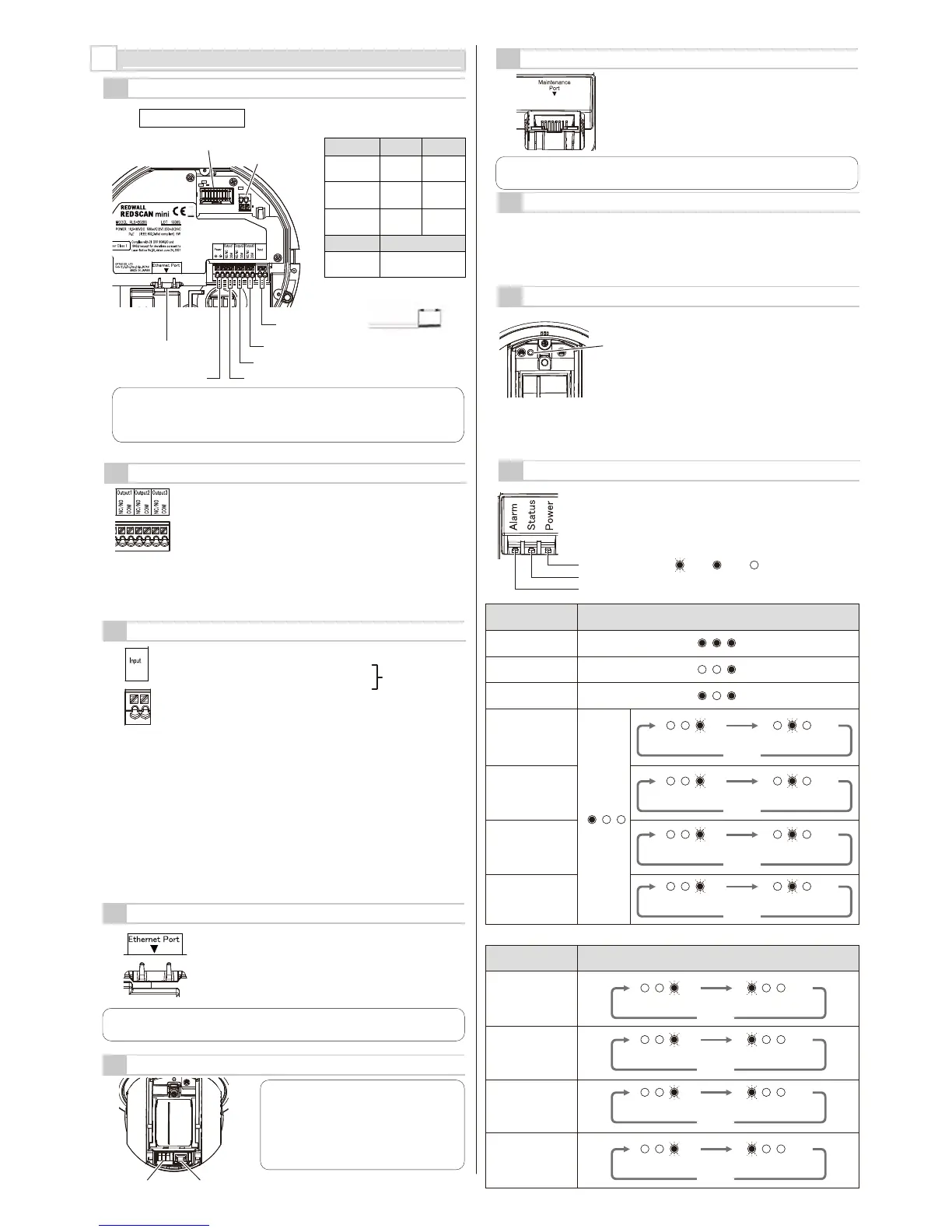
WIRING
Inside the base
The length of the power wire
must be less than the figures
listed below.
Stripping length
m (ft)
Wire size
12VDC 24VDC
AWG18
(0.83 mm
2
)
AWG20
(0.52 mm
2
)
30
(100)
AWG16
(1.31 mm
2
)
Strip the cover of the
wiring about 9 mm.
9 mm
Cable
PoE (IEEE802.3 standard)
Cat5e or
above
50
(160)
80
(260)
790
(2590)
1260
(4130)
2000
(6560)
100
(320)
Relay connector
Signal input
(RLS-2020S only)
Signal output 3
Signal output 2
Signal output 1Power supply input
Wall tamper input
Ethernet port (PoE)
5-9
LED INDICATOR
Stand-by
Alarm
Anti-masking
Anti-rotation
Soiling
Environmental
disqualification
(DQ)
Red
Yellow
Green
Blink Light OFF
Detector condition
Warm-up
(apprpx. 60 s)
LED
*
* According to alarm status.
Motor error
Hardware error
Over heat
Others
(not fixed the laser
window properly, etc.)
Trouble condition
LED
Green blinks once. Yellow blinks once.
Green blinks once. Yellow blinks twice.
Green blinks once. Yellow blinks 3 times.
Green blinks once. Yellow blinks 4 times.
x 2
x 3
x 4
Green blinks once. Red blinks once.
Green blinks once. Red blinks twice.
x 2
Green blinks once. Red blinks 3 times.
x 3
Green blinks once. Red blinks 4 times.
x 4
REPEAT
REPEAT
REPEAT
REPEAT
REPEAT
REPEAT
REPEAT
REPEAT
Note >>
Some PoE netwok switches have a limit for wattage. Connect the detectors
to PoE network switches without exceeding the limit referring to their
instructions.
5-8
INITIALIZATION TO FACTORY DEFAULT
5-7
POWERING ON
Enter the DC power to the power supply input terminal.
Or, connect PoE power supply equipment to the ethernet port (PoE)
.
After power on, all the indicators are turned on for approx. 60 seconds and then
the status and alarm indicators are turned off.
During this period, REDSCAN mini itself performs initial settings.
Reset button
1. Turn Off the power supply. Remove
the front cover and laser window.
(refer to 3-1,3-3)
2.
Power On while pressing the reset button.
3. All LEDs turn On. Red LED turns Off
after 50 sec, and green LED turns Off
after 2 sec. And then, release the reset
button.
Yellow LED turns off after 3 sec.
4. Turn Off the power supply.
Attach the laser window and the front
cover. Then, Power On.
* As for wiring for UL application, refer to UL statement on the end of page 11.
5-4
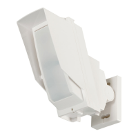
ETHERNET PORT (PoE)
5-5
MAINTENANCE SECTION
The Ethernet port inside the base is for constant
connection. PoE is supported.
LED indicator Maintenance port
Default
IP address : 192.168.0.126
Subnet mask : 255.255.255.0
Default gateway : 192.168.0.1
Note >>
At a maintenance port, Use a light LAN
cable for indoor use. (Do not use the
heavy LAN cable for exterior use.)
This port is for maintenance purpose.
After maintenance, re-assemble the front
cover.
Note >>
Do not use the same subnet for the main Ethernet port and the Maintenance port.
Programmable input can be used for the following functions.
・
Signal Output 1 for confirmation of the function
・
Signal Output 2 for confirmation of the function
・
Signal Output 3 for confirmation of the function
When the signal input is closed, the signal output (1 to 3)
responds as change the status of output. It can be used for
confirmation that the detector is operated properly.
・ Switching to Next Masking / Allocating file
When the signal input is closed, the unit changes Masking/Area
Allocation pattern files. e.g. File 1 to File 2, File 2 to File 3, File 3
to File 4 and File 4 to File 1... It can be used for switching
Masking/Allocation pattern remotely without REDSCAN Manager.
・Area Set
When the signal input is closed, Area set is started.
It can be used for re-creating the detection area without
REDSCAN Manager.
For settings this function, the dedicated software, REDSCAN Manager is required.
If signal input is closed shorter time than the judgement time (Default 1 sec.,
adjustable range 1 to 10 sec), it will be ignored.
5-6
MAINTENANCE PORT
The Ethernet port on the maintenance section is
connected only for initial set-up. Do not use it for
constant connection.
Default
IP address : 192.168.1.126
Subnet mask : 255.255.255.0
Note >>
Do not use the same subnet for the main Ethernet port and the Maintenance port.
*Refer to UL statement
on the end of page11