I/O Connections 16
4.
The I/O terminals are located in the center of
the wiring compartment, as shown previously in
Figure9.
The Digital Input connections (I1 and I2) are used to
control the Drive based on the state of an external
device, such as a flow switch, moisture sensor,
alternator, or other device. Programming is needed
to activate any of these functions (see Table 5).
The Output Relay (O1) is used to control an external
devicebasedontwostatesofDrive;eitherRunning
the pump or Faulted. Programming is needed to
activate any of these functions (see Table 5).
Cable Installation
Three 1/2” conduit knockouts are provided on the
bottom of the Drive enclosure for the I/O wires.
Breakouttheclosest1/2”knockoutandroutethe
wires through. Use a cord grip to prevent the wire
from rubbing and causing a short.
NOTICE Never run low voltage I/O wire through
the same conduit hole as the 230V input wires or
motor wires.
To connect the external wires to the terminals:
1. Strip wire ½ inch
2. Push spring terminal up with finger or slotted
screwdriver
3. Insert wires from bottom
4. Release spring terminal
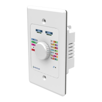
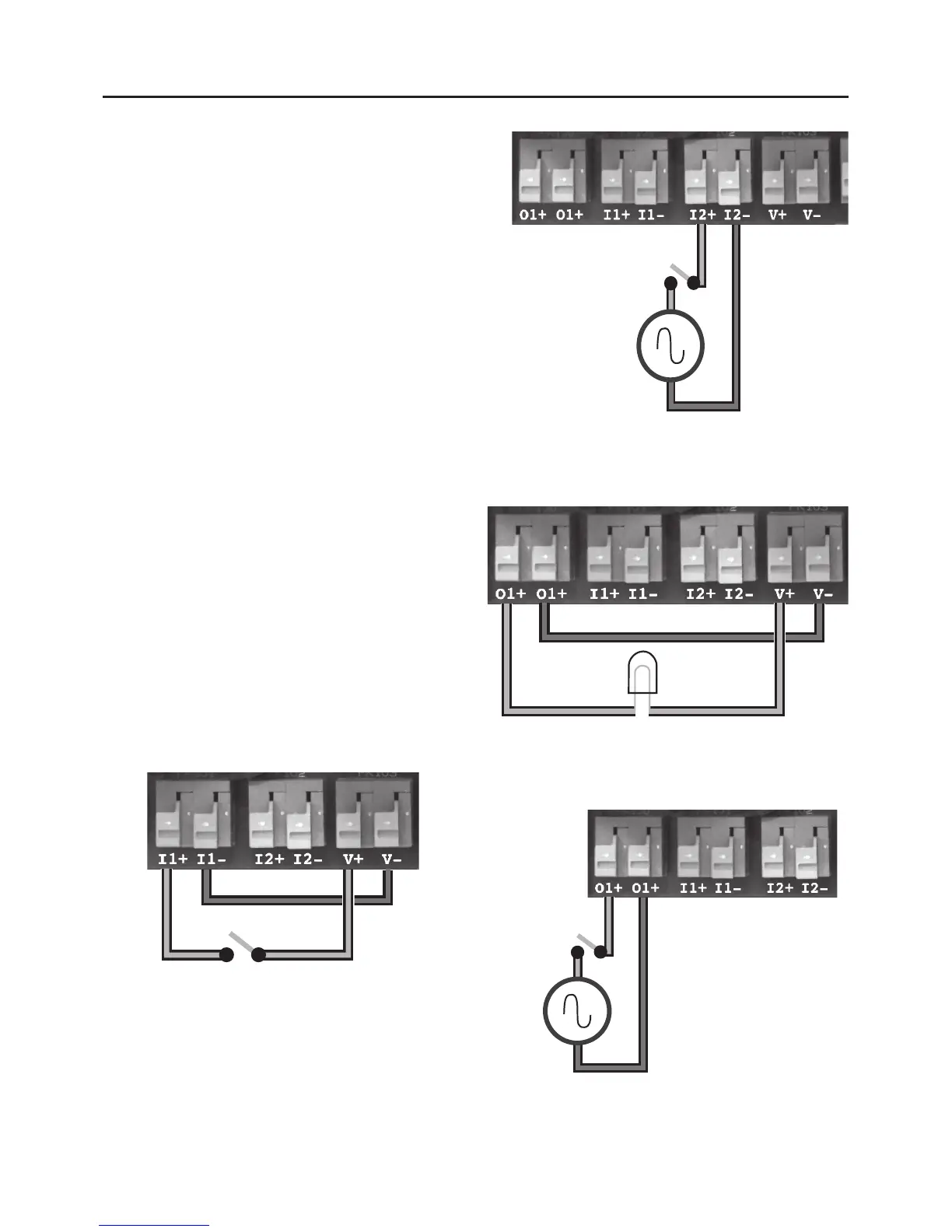
Connection Examples
Figures 15-18 show various connection schemes
for typical applications. Table 6 describes each I/O
terminal, including purpose and rating.
 Loading...