EasyManua.ls Logo

Phoenix Contact INTERBUS series User Manual

Phoenix Contact INTERBUS series
56 pages
To Next Page IconTo Next Page
To Previous Page IconTo Previous Page
Page #47 background image
onlinecomponents.com
INTERBUS Loop
6057AC01 1-43
Addressing None
Cycle time 3.7 ms with 1000 I/Os
Components All digital, analog and "intelligent" I/O devices
INTERBUS Loop System Basic Specifications
INTERBUS Loop Modules Current Consumption (mA) From the
Installation Local Bus
IBSL BOX AI 2/2-M12 60, typical
IBSL BOX AO 1/2/I M12(-D) 80, typical
IBSL BOX AO 1/2/U M12(-D) 80, typical
IBSL BOX 24 DI 2/2-M12(-D) 32, typical
IBSL BOX 24 DI 4/4-M12(-D) 32, typical
IBSL BOX 24 DIO 2/2/4-M12-2A(-D) 34, typical
IBSL BOX 24 DO 2/2-M12-2A(-D) 33, typical
IBSL BOX 24 DO 4/4-M12-2A (-D) 37, typical
IBSL BOX TEMP 2/2 M12 30, typical
BK Modules for INTERBUS Loop Current Output
IB SL 24 BK-LK Power consumption of the module electronics:
2 W at nominal voltage;
Permissible load current: 1.5 A
IB SL 24 BK-T
IB SL IP 24 BK-T
Question and Answer IconNeed help?

Do you have a question about the Phoenix Contact INTERBUS series and is the answer not in the manual?

Phoenix Contact INTERBUS series Specifications

General IconGeneral
BrandPhoenix Contact
ModelINTERBUS series
CategoryControl Unit
LanguageEnglish

Summary

INTERBUS Loop Overview

1.1 Product Description

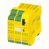
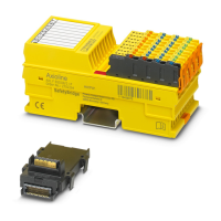
Describes INTERBUS Loop modules, their connection, types, and protection levels.

Basic Specifications

Lists technical specifications like cable length, distance, module count, and current capacity.

INTERBUS Loop Installation Example

INTERBUS Module Structure

Module Diagnostic and Status Indicators

1.4.1 Diagnostic Indicators of BK Modules

Explains diagnostic LEDs (UL, RC, BA, E, LD, RD) for BK modules and their meanings.

1.4.2 Diagnostic and Status Indicators of Modules

Explains diagnostic LEDs (US, DIAG) for general modules and their meanings.

INTERBUS Module Mounting Distances

INTERBUS Module Dimensions

INTERBUS Module Mounting Procedures

1.7.1 Mounting BK Modules with IP 20 Protection

Details how to mount BK modules with IP 20 on a mounting rail, including grounding.

1.7.2 Mounting BK Module with IP 65/IP 67 Protection

Details how to mount BK modules with IP 65/IP 67 directly on a surface, including grounding.

1.7.3 Mounting INTERBUS Loop Modules

Details how to mount INTERBUS Loop modules (IP 65/IP 67) on profiles or flat surfaces.

INTERBUS Connection Procedures

1.8.1 Connecting Remote Bus (BK Module IP 20)

Explains assembly of MINI-COMBICON connectors for remote bus.

1.8.2 Connecting Remote Bus with Fiber Optics

Details fiber optic remote bus connection, switch settings, and connectors.

1.8.3 Connecting Installation Remote Bus (BK Module IP 65/IP 67)

Details connecting installation remote bus for IP 65/IP 67 modules, including hood prep.

1.8.4 Connecting INTERBUS Loop (IP 20 BK Module)

Explains ring structure and initial connection steps for the installation local bus.

INTERBUS Initial Startup

Connecting and Testing Installation Local Bus

Describes steps for initial startup, connecting local bus and testing.

Connecting Sensors and Actuators

Related product manuals