DJM-800
152
1234
1234
C
D
F
A
B
E
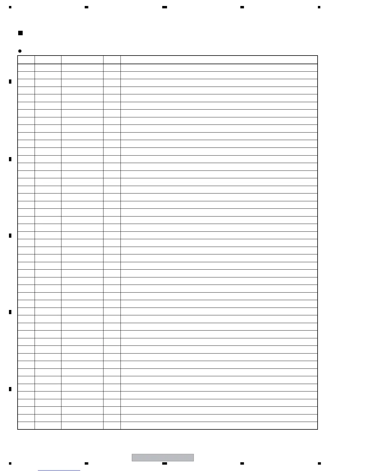
7.4 IC INFORMATION
No. Mark Pin Name I/O Pin Function
1 MD2 I Mode pin 2 NOR: Mode 4 At rewriting: Mode 3
2 VSS
MD2
VSS I GND
3 P80 MUTE O MUTE signal 0: Mute ON, 1: Mute OFF
4 VCC VCC I Power supply
5A0A0OAddress bus output A0
6A1A1OAddress bus output A1
7A2A2OAddress bus output A2
8A3A3OAddress bus output A3
9A4A4OAddress bus output A4
10 VSS VSS I GND
11 A5 A5 O Address bus output A5
12 A6 A6 O Address bus output A6
13 A7 A7 O Address bus output A7
14 A8 A8 O Address bus output A8
15 A9 A9 O Address bus output A9
16 A10 A10 O Address bus output A10
17 A11 A11 O Address bus output A11
18 VSS VSS I GND
19 PB4 DIGIANA1 I CH1 Digital <-> Analog SW
20 PB5 DIGIANA2 I CH2 Digital <-> Analog SW H : Digital, L : Analog
21 PB6 DIGIANA3 I CH3 Digital <-> Analog SW H : Digital, L : Analog
22 PB7 DIGIANA4 I CH4 Digital <-> Analog SW H : Digital, L : Analog
23 PA0 XDONE I FPGA program ready H : Digital, L : Analog
24 PA1 XPGM O FPGA program clear
25 VSS VSS I GND
26 PA2 DSP_RESET O RESET OUT H : Release of RESET, L : RESET
27 PA3 FPGA_RESET O RESET OUT H : Release of RESET, L : RESET
28 PA4 DIGIANA_SEL1 O CH1 input select 0: Analog side 1, 1: Digital side 1
29 PA5 DIGIANA_SEL2 O CH2 input select 0: Analog side 2, 1: Digital side 2
30 PA6 DIGIANA_SEL3 O CH3 input select 0: Analog side 3, 1: Digital side 3
31 PA7 DIGIANA_SEL4 O CH4 input select 0: Analog side 4, 1: Digital side 4
32 EMLE EMLE I Emulator enable pin Set to L level at normal operation. GND by 1k.
33 TXD3 MIDI_TXD O MIDI TXD send only
34 P82 SIO_SEL0 O SIO port select 0 FPGA, DAC, selection (at power on) H : FPGA, L : DAC
35 PH0 SIO_SEL1 O SIO port select 1 DIT selection L : DIT
36 PH1 SIO_SEL2 O SIO port select 2 EEPROM selection
37 PH2 SIO_SEL3 O FPGA_SIO0 DIR (CH1,CH3) selection L : DIR
38 PH3 SIO_SEL4 O FPGA_SIO1 DIR (CH2,CH4) selection L : DIR
39 WDTOVFn EMU_03 O Overflow output of the watch dock timer for H8JTAG emulator
40 NMI NMI I Nonmaskable interrupt L level fixing
41 VCC VCC I Power supply
42 P10 SW_MAT0 I KEY matrix b0 input
43 P11 SW_MAT1 I KEY matrix b1 input
44 P12 SW_MAT2 I KEY matrix b2 input
45 P13 SW_MAT3 I KEY matrix b3 input
46 P14 SW_MAT4 I KEY matrix b4 input
47 P15 SW_MAT5 I KEY matrix b5 input
48 P16 SW_MAT6 I KEY matrix b6 input
DYW1757(HD64F2377) : (DSP ASSY : IC 1)
• Microcomputer
Pin Function
 Loading...