En
30
03 Connecting your equipment
2 Connect a TV monitor to the VIDEO
ZONE 3 OUT jack on this receiver.
PRE OUT
2
SURROUND SURR BACK F HEIGHT F WIDE FRONT
(
CD
))
GNABLE
IN
2
(
DVR/BDR
)(
TV/SAT
)
OPTICAL
ASSIGNABLE
IN
1
IN
2
IN
3
(
VIDEO
)
AD
DC OUTPUT
WIRELESS LAN
(
10/100
)
LAN
(
OUTPUT
5 V
0.6 A MAX
)
L RL
(
Single
)
FRONT WIDE /
B
RS-232C
ZONE 2
IN
OUT
ZONE 3
OUT
TDVD
COMPONENT VIDEO
YP
B
P
R
ASSIGNABLE
MONITOR
OUT
ZONE2
OUT
(
DVD
)
IN
1
(
DVR/
BDR
)
IN
2
(
VIDEO
)
IN
3
CU-RF100
SPEAKER
FM UNBAL 75
AM LOOP
ANTENNA
(
OUTPUT 5 V
150 mA MAX
)
CONTROL
IR
OUT
IN
OUT
IN
1
IN
2
2
1
12 V TRIGGER
(OUTPUT 12 V
TOTAL 150 mA MAX)
HDMI
(VIDEO)
IN
1
IN
2
IN
4
ASSIGNABLE
1 6
VIDEO IN
RL
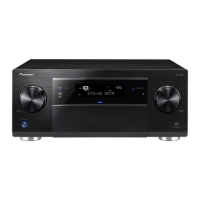
Sub zone (ZONE 3)
Main zone
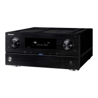
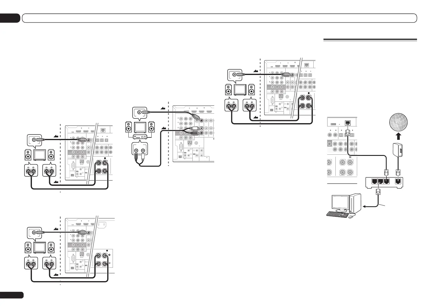
Connecting to the network
through LAN interface
By connecting this receiver to the network via
the LAN terminal, you can listen to Internet
radio stations. To listen to Internet radio sta-
tions, you must sign a contract with an ISP
(Internet Service Provider) beforehand.
When connected in this way, you can play audio
files stored on the components on the network,
including your computer, using HOME MEDIA
GALLERY inputs.
PRE OUT
FER
2
SURROUND SURR BACK F HEIGHTF WIDEFRO
(
CD
)(
DVD
)
LE
IN
1
IN
2
(
DVR/BDR
)(
TV/SAT
)
OPTICAL
ASSIGNABLE
IN
1
IN
2
IN
3
(
VIDEO
)
DC OUTPUT
for WIRELESS LAN
(
10/100
)
LAN
(
OUTPUT
5 V
0.6 A MAX
)
LR L
(
Single
)
FRONT WIDE /
B
HT
WAN
321
LAN
Internet
Modem
Router
LAN cable
(sold separately)
to LAN port
PC
Connect the LAN terminal on this receiver to
the LAN terminal on your router (with or with-
out the built-in DHCP server function) with a
straight LAN cable (CAT 5 or higher).
Turn on the DHCP server function of your
router. In case your router does not have the
built-in DHCP server function, it is necessary
to set up the network manually. For details, see
Network Setup menu on page 89.
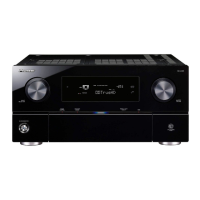
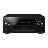
1 Connect a pair of speakers to the
surround back or front wide speaker
terminals.
2 Connect a TV monitor to the VIDEO
ZONE 2 OUT jack on this receiver.
SC-LX85 only:
! COMPONENT VIDEO ZONE 2 OUT can be
used to output clear images.
! The GUI screen is not displayed if only the
COMPONENT VIDEO ZONE 2 OUT jack is
connected.
To use the front wide speaker terminals for
ZONE 2:
PRE OUT
2
SURROUND SURR BACK F HEIGHT F WIDE FRONT
(
CD
)
D
)
SIGNABLE
1
IN
2
(
DVR/BDR
)(
TV/SAT
)
OPTICAL
ASSIGNABLE
IN
1
IN
2
IN
3
(
VIDEO
)
(
O
ADA
DC OUTPUT
r WIRELESS LAN
(
10/100
)
LAN
(
OUTPUT
5 V
0.6 A MAX
)
L RL
(
Single
)
FRONT WIDE /
B
RS-232C
ZONE 2
OUT
ZONE 3
OUT
COMPONENT VIDEO
YP
B
P
R
ASSIGNABLE
MONITOR
OUT
ZONE2
OUT
(
DVD
)
IN
1
(
DVR/
BDR
)
IN
2
(
VIDEO
)
IN
3
CU-RF100
FM UNBAL 75
AM LOOP
ANTENNA
(
OUTPUT 5 V
150 mA MAX
)
CONTROL
IR
OUT
IN
OUT
IN
1
IN
2
2
1
12 V TR
(OUTPUT
TOTAL 15
HDMI
(VID
IN
1
IN
2
IN
ASSIGNABLE
1 6
VIDEO IN
RL
Sub zone (ZONE 2)
Main zone
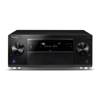
To use the surround back speaker terminals for
ZONE 2:
H IN
L
R
ACK
SURROUND BACK
L RL
(
Single
)
A
AC IN
RS-232C
ZONE 2
OUT
ZONE 3
OUT
COMPONENT VIDEO
YP
B
P
R
ASSIGNABLE
MONITOR
OUT
ZONE2
OUT
(
DVD
)
IN
1
(
DVR/
BDR
)
IN
2
(
VIDEO
)
IN
3
CU-RF100
FM UNBAL 75
AM LOOP
ANTENNA
(
OUTPUT 5 V
150 mA MAX
)
CONTROL
IR
OUT
IN
OUT
IN
1
IN
2
2
1
12 V TR
(OUTPUT
TOTAL 15
HDMI
(VID
IN
1
IN
2
IN
ASSIGNABLE
1 6
VIDEO IN
RL
Sub zone (ZONE 2)
Main zone
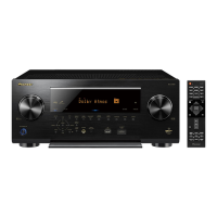
Secondary MULTI-ZONE setup
(ZONE 3)
1 Connect a separate amplifier to the
AUDIO ZONE 3 OUT jacks on this receiver.
You should have a pair of speakers attached to
the sub zone amplifier as shown in the follow-
ing illustration.
2 Connect a TV monitor to the VIDEO
ZONE 3 OUT jack on this receiver.
RS-232C
ZONE 2
IN IN
OUT
ZONE 3
OUT
TV/SAT VDVD
COMPONENT V IDEO
YP
B
P
R
ASSIGNABLE
MONITOR
OUT
ZONE2
OUT
(
DVD
)
IN
1
(
DVR/
BDR
)
IN
2
(
VIDEO
)
IN
3
CU-RF100
R
SPEAKERS
A
FM UNBAL 75
AM LOOP
ANTENNA
(
OUTPUT 5 V
150 mA MAX
)
CONTROL
IR
OUT
IN
OUT
IN
1
IN
2
2
1
12 V TRIGGER
(OUTPUT 12 V
TOTAL 150 mA MAX)
HDMI
BD IN
(VIDEO)
IN
1
IN
2
IN
4
ASSIGNABLE
1 6
RL
AUDIO IN
VIDEO IN
Sub zone (ZONE 3) Main zone
Secondary MULTI-ZONE setup using
speaker terminals (ZONE 3)
You must select 5.1ch + ZONE 2+3 in Speaker
system setting on page 87 to use this setup.
1 Connect a pair of speakers to the front
wide speaker terminals.
You should have a pair of speakers attached to
the sub zone amplifier as shown in the follow-
ing illustration.
 Loading...