EasyManuals Logo

Pioneer SX-1080 Service Manual

Pioneer SX-1080
65 pages
To Next Page IconTo Next Page
To Previous Page IconTo Previous Page
Page #18 background imageLoading...
Page #18 background image
Fig.
3
Block
diagram
of
PA1002-A
AM
Tuner
The
AM
tuner
employs
a
2-stage
variable
capaci¬
tor,
one
IC
(HA1197)
and
one
AM
ceramic
filter.
Its
block
diagram
is
given
in
Fig.
4.
HA1197
is
an
IC
containing
an
RF
amplifier,
converter,
2-stage
IF
amplifier,
detector,
and
AGC
circuit,
and
features
excellent
AF
frequency
response
and
distortion.
Qj
of
the
output
circuit
is
a
special
AM
muting
circuit.
This
circuit
is
operated
until
the
AM
tuner
stabilizes
immediately
after
the
FUNCTION
AM
switch
has
been
set
to
ON.
The
instant
the
AM
switch
is
set
to
ON,
+B
is
supplied
to
Rr,
thru
C
9
,
and
the
base
of
Q,
is
forward
biased.
Consequently,
Q,
is
turned
ON,
and
the
AM
output
signal
is
shorted
to
ground
during
the
time
constant
of
C
9
,
Rg.
8.2
P
HONO,
MIC
INPUT
CIRCUIT
PHONO
1,
PHONO
2/MIC
input
switching
is
performed
by
the
switch
and
the
MIC
jack.
When
a
microphone
plug
is
inserted
into
the
MIC
jack,
the
input
is
switched
to
MIC
at
both
the
L
and
R
channels.
Since
the
IC
(HA1457)
is
used
as
both
a
microphone
amp
and
equalizer
amp,
a
circuit
having
a
reverse
RIAA
curve
is
provided
at
the
MIC
input
circuit
to
obtain
a
flat
frequency
response.
8.3
FLAT
AMPLIFIER
The
power
amplifier
is
an
all-stage
direc1>coupled
circuit.
It
amplifies
the
signal
to
the
required
level
and
sends
a
low
impedance
signal
to
the
tone
control
circuit.
8.4
TONE
CONTROL
The
tone
control
circuit
is
an
NFB
type
inserted
in
front
of
the
power
amp.
Bass
turnover
(200Hz
400Hz)
and
treble
turnover
(2.5kHz
<—
5kHz)
switches
and
a
tone
defeat
circuit
which
bypasses
the
tone
control
circuit
to
obtain
a
flat
characteristic
are
provided,
in
addition
to
variable
resistor
which
adjusts
the
rise
and
fall.
8.5
POWER
AMPLIFIER
The
power
amplifier
is
an
all-stage
direct-coupled
pure
complementary
OCL
circuit
having
a
differen¬
tial
amplifier
at
the
first
stage,
current
mirror
cir¬
cuit
at
the
predriver
stage
and
a
parallel
push-pull
amplifier
at
the
final
stage
(Fig.5).
The
first
stage
(Q,)
is
a
PNP
type
dual
transistor
differential
amplifier
that
amplifies
the
input
signal
and
stablizes
the
center
voltage
of
the
power
stage.
Q
3
and
Q
4
are
driven
by
the
opposite
phases
of
the
output
of
Qi.
The
output
of
Q
4
is
applied
to
the
current
mirror
circuit
consisting
of
D
2
and
Qs
and
phase
inverted.
Consequently,
Q
3
and
Qs
are
in-
phase
signals,
and
are
operated
as
a
push-pull
pre¬
driver.
Low
distortion
and
improved
rise
charac¬
teristic
at
high
amplitudes
have
been
realized
by
making
the
predriver
stage
push-pull.
Overcurrent
is
detected
and
destruction
of
the
power
transistor
prevented
by
Qg.
The
final
stage
is
a
parallel
connected
power
amplifier.

Questions and Answers:

Question and Answer IconNeed help?

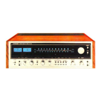
Do you have a question about the Pioneer SX-1080 and is the answer not in the manual?

Pioneer SX-1080 Specifications

General IconGeneral
Total Harmonic Distortion0.1% (at rated power)
Tuning RangeFM, MW
Damping Factor30
Input Sensitivity2.5mV (MM), 150mV (line)
Output150mV (line), 1V (Pre out)
Speaker Load Impedance4Ω to 16Ω
Frequency Response5Hz to 100kHz
Signal to Noise Ratio90dB (line)
Semiconductors4 x FET, 6 x IC
Power Output120 watts per channel (8 ohms, 20Hz-20kHz)

Related product manuals