EasyManuals Logo

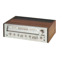
Pioneer SX-750 Service Manual

Pioneer SX-750
89 pages
To Next Page IconTo Next Page
To Previous Page IconTo Previous Page
Page #14 background imageLoading...
Page #14 background image
5.3
FM
MUTING
CIRCUIT
At
time
of detuning
(more
than
t
70kHz) and
with
an antenna
input
of less
than
10dB
(OdB
=
1pV),
a
DC
voltage
is
produced
at
pin
12 of
IC,
(HAl137).
This
voltage
is
employed
as
the
muting
trigger.
With
the MUTING
switch
ON,
Q1
becomes ON
and
Q2
OFF
in
the
Q1-{2
Schmitt
circuit
as
the
muting
trigger
is
produced.
Q3
becomes ON
when
Q2
is OFF,
and
Q4, Q5
and
Q6
also become
ON.
With
q4
&
Qb
ON,
the
FM
output
becomes
grounded,
while IC,
output
is
grounded
by
Q6
to
apply
muting.
Fig.
5 FM Muting Circuit
5.4 PHONO
EOUALIZER
AMPLIFIER
IC
(TA7136P1)
is used
with independent left
and
right channels. Grade
G
styrole capacitors
and
grade
F
metal film
resistors comprise
the
equal-
izer
elements,
leading
to an RIAA
deviation
within 0.2dB from
30Hz
to 15kHz.
sx-75Cl
5.5
MICROPHONE
CIRCUIT
A 2
stage transistor
amplifier
(monophonic)
is
provided
in addition
to the
phono
equalizer
ampli-
fier. A
selector switch
cuts
the
AUX
jack
input
when a
plug
is inserted
into the
MIC
jack.
The
amplified microphone
signal is then supplied
to
both
the
left
and right
channels. The
FUNCTION
switch is set
to the
AUX
position
when
using
a
microphone.
Function
SW
.
B
Lch
AUX
Fis.
7
5.6
TONE CONTROL
CR
type
tone controls
are connected
to an
ex-
tremely
low output
impedance
flat
applifier
(IC
=
T47136,
31dB
gain).
Bass
can
be
varied
in
the range
of
+343
-
-7dB
(100H2)
and treble in
the range
of
+943
-
-
7dB
(10kHz).
A
TONE
switch
also
allows
the tone
controls
to be switch
ON/OFF.
R1
and R2
arc
designed
to
provide
the same loss
when
the TONE
switch
is OFF
as obtained
with
the TONE
switch
ON
and the BASS
and
TREBLE
controls
at center
positions
(flat).
Frequency
response
thus
becomes
flat
when the TONE
switch is
set
to OFF.
R3,
and
Cl form
a 6kHz
6dB/octave HIGH
CUT
filter
which
is connected
following
the TONE
switch.
Fig.
6
Fis.8
4E
FurLction
5V
TA''t136P-r
TA'r
|
36

Questions and Answers:

Question and Answer IconNeed help?

Do you have a question about the Pioneer SX-750 and is the answer not in the manual?

Pioneer SX-750 Specifications

General IconGeneral
Signal to Noise Ratio75dB (MM), 90dB (line)
Tuning RangeFM, MW
Damping Factor30
Power Output50 watts per channel (8 ohms, 20Hz-20kHz)
Frequency Response10Hz to 50kHz
Total Harmonic Distortion0.3%
Input Sensitivity2.5mV (MM), 150mV (line)
Output150mV (line)
Speaker Load Impedance4Ω to 16Ω

Related product manuals