EasyManuals Logo

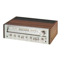
Pioneer SX-750 Service Manual

Pioneer SX-750
89 pages
To Next Page IconTo Next Page
To Previous Page IconTo Previous Page
Page #19 background imageLoading...
Page #19 background image
6.3
MPX
Adjustment
1.
Oonnect measuring
equipment
as shown in
Fig.16.
2.
T\rne
FM
SG and
SX-750 to
dial readings of
98MHz.
3.
Set
FM
SG
for
60dB
unmodulated
output.
4. Connect
the
output signal
(19kHz)
of
MPX
SG
PILOT
OUT
terminal to the
horizontal
input
of
an
oscilloscope,
and
pin
20 of the tuner assembly
(AWE-073)
via
a
probe
to the oscilloscope
vertical
input.
5. Adjust
VR2
so
that
lissajous
pattern
displayed
on
oscilloscope becomes stationary
(Fig.
16).
6.
Set
MPX
SG to 67.5kHz
deviation at lkHz
for
left and right channels,
and
to 7
.1kHz deviation
for 19kHz
pilot
signal.
7.
Adjust
T5 core for
minimurn audio
frequency
distortion. Take
care to turn core only
within
t180'.
8.
Adju.st
VR3
for
minimum
signal leakage
from R
channel
to
L channel,
and from L channel to
R
channel.
OscilloscoPe
Lissajous
AC
voltmeter
Distortion
meter
"[Em
,/
|
1V
Fis.
16

Questions and Answers:

Question and Answer IconNeed help?

Do you have a question about the Pioneer SX-750 and is the answer not in the manual?

Pioneer SX-750 Specifications

General IconGeneral
Signal to Noise Ratio75dB (MM), 90dB (line)
Tuning RangeFM, MW
Damping Factor30
Power Output50 watts per channel (8 ohms, 20Hz-20kHz)
Frequency Response10Hz to 50kHz
Total Harmonic Distortion0.3%
Input Sensitivity2.5mV (MM), 150mV (line)
Output150mV (line)
Speaker Load Impedance4Ω to 16Ω

Related product manuals