5.7
PROTECTION
CIRCUIT
This
protection
circuit
functions
to
protect
the
speakers and the
power
amplifiers from damage
due to short-circuit of the load, etc.,
and
performs
a muting
operation to cut noise and distortion
which occur when switching the
power
on and off.
The
circuit is shown
in Fig.
15, and consists
of a
bridge
type over-current and overload
detector, a
differential
amplifier DC voltage detector,
and a
power
switch
ON/OFF detector section.
Relay
Driving
Circuit
Q4-Q6,
in
Fig.
9,
comprise the
relay driving
circuit.
In
the
normal condition
reverse bias is applied
to
the base of
Q4,
and
Q4
is in
a
off state.
When
one of
the above mentioned detection
circuits
goes
or, current flows
through
R11, the
base
potential
falls
and
Q4
is
turned
on.
Consequently
Qb
comes on and
Q6
goes
off. When
Q6
goes
off,
the
current of
the relay circuit is cut, to
release
the switch of
the
output
circuit.
When the
power
switch is turned on, a
delay
operation occurs in this circuit. R17 and C3, in the
base
circuit
of
Q6,
are the
time constant elements
which determine the
delay
time.
When the
power
switch
is tumed on, C3 charges
to a
potential
of
+60
volts
through
R17 and R18, and
Q6
is
kept in
the
off
state during this time.
When the
power
source
is switched off, the
muting operation
of
Qb
prevents
shock noise.
In
the
normal
condition,
the
potentials
of
+33
volts
and
-
5.1
volts
are applied
to
Qb
through RL4 and R15. The
resultant
poten-
tial
at
the
base of
Q5
is
-1
volt in
the
cutout
condition. When the
power
supply is turned off,
PoY|er
amplifier
0Yer-current
and
overload
detection circuit
of
-
5.1
volts
disappears
immediately due
to the
small time constant
of
the
power
circuit. Thus a
positive
base
potential
remains, switching
Qb
on,
which in
turn switches off
Q6
and
hence
the relay.
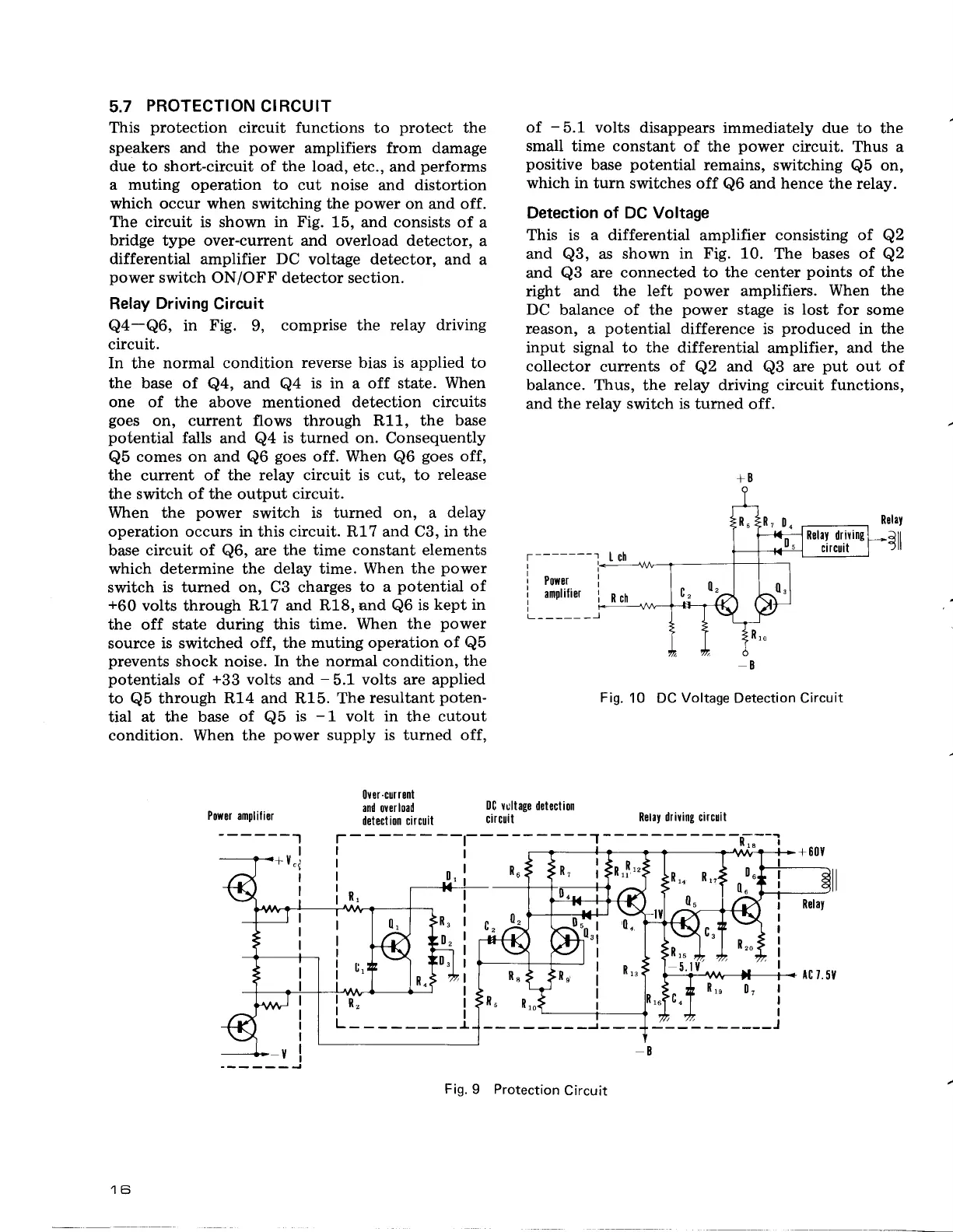
Detection of DC Voltage
This is a differential amplifier consisting of
Q2
and
Q3,
as shown in
Fig. 10.
The bases of
Q2
and
Q3
are connected
to the center
points
of
the
right and the
left
power
amplifiers.
When the
DC
balance of
the
power
stage
is lost for
some
r€ason,
a
potential
difference is
produced
in the
input signal to the differential
amplifier, and
the
collector
currents of
Q2
and
Q3
are
put
out of
balance.
Ttrus, the
relay
driving
circuit functions,
and the
relay switch
is tumed off.
tr
-------l
+B
Ich
Ru
R- n
-fiRelaydriring
ci
rcuit
Rch
n
0,
Iv- It'
0"
\"
R
ro
B
L----_
--l
Fig.
10 DC
Voltage
Detection Circuit
RelaY
-arl
ftl
Power
amplilier
IlC
vultage detectioll
circuit
*Y"l
I
I
Retay driving circuit
o,
I
R6
c")
Fig.
9 Protection
Circuit
 Loading...