f,
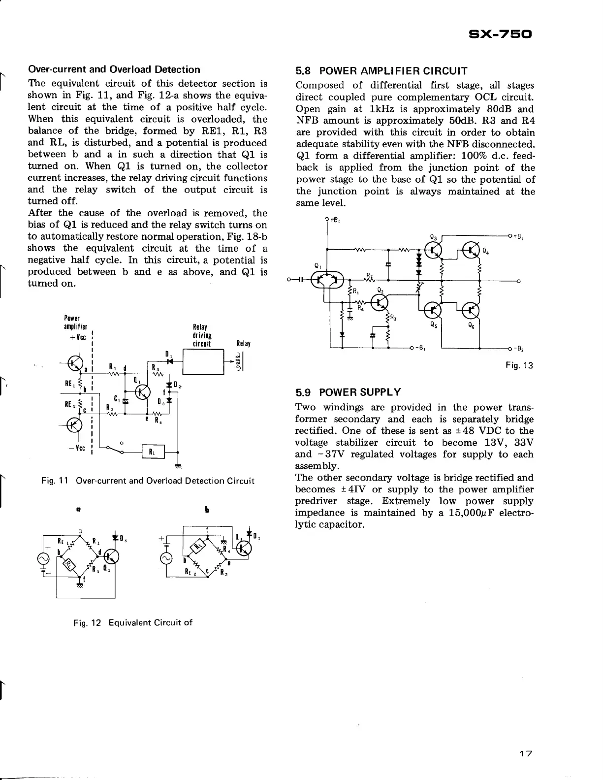
Over-current and
Overload Detection
The equivalent
circuit of this detector
section is
shown in
Fig.
11,
and
Fig.
L2-a shows
the equiva-
lent
circuit at the time of
a
positive
half
cycle.
When
this
equivalent
circuit is overloaded,
the
balance of the
bridge, formed by
RE1, R1, Rg
and RL, is disturbed,
and a
potential
is
produced
between b
and a in such
a direction
that
Q1
is
turned
on. When
Ql
is turned on,
the collector
current increases,
the relay driving circuit functions
and the relay
switch of the
output circuit is
turned
off.
After
the cause
of the overload is
removed, the
bias of
Ql
is
reduced
and the
relay
switch
turns on
to
automatically
restore
normal
operation,
Fig.
18-b
shows
the equivalent
circuit
at the time of a
negative
half
cycle. In
this
circuit,
a
potential
is
produced
between
b and e as above, and
Q1
is
tumed on.
Powsr
amplilier
+
Vcc
Fig.
11
Over-current and Overload Detection
Circuit
FiS.
12
Equivalent Circuit
of
sx-75cl
5.8 POWER
AMPLIFIER CIRCUIT
Composed of
differential
first
stage, all stages
direct coupled
pure
complementary OCL circuit.
Open
gain
at lkHz is
approximately
80dB
and
NFB
amount is approximately 50dB. R3
and R4
are
provided
with this circuit in order
to obtain
adequate stability
even with the
NFB
disconnected.
Ql
form
a differential
amplifier
LOOVo d.c. feed-
back is
applied
from
the
junction
point
of the
power
stage to
the base of
Q1
so the
potential
of
the
junction
point
is always maintained
at
the
same level.
Fis.
13
5.9
POWER SUPPLY
Two
windings are
provided
in the
power
trans-
former
secondary
and each
is
separately bridge
rectified. One
of these is sent as
148
VDC to the
voltage stabilizer
circuit to become 13V, 33V
and
-37V
regulated
voltages for
supply to each
assembly.
The
other secondary voltage is
bridge
rectified
and
becomes
t
4IV or supply
to the
power
amplifier
predriver
stage.
Extremely
low
power
supply
impedance
is maintained
by a 15,000pF
electro-
lytic capacitor.
17
 Loading...