ELECTRICAL
5.7
CHARGING SYSTEM TESTING
CAUTION: Do not connect or disconnect the battery cable or ammeter with the engine running.
CAUTION: Never use the electric starter with the ammeter connected, or damage to the meter or meter fuse may
result. Do not run test for extended period of time. Do not run test with high amperage accessories.
The “break even” point of the charging system is the point at which the alternator overcomes all system loads
(lights, etc.) and begins to charge the battery. Depending on battery condition and system load, the break even
point may vary slightly. The battery should be fully charged before performing this test.
SConnect an ammeter (set to DC amps) in series be-
tween the negative battery cable and terminal.
SConnect a tachometer according to manufacturer’s in-
structions.
SWith engine off and the key and kill switch in the ON
position, the ammeter should read negative amps
(battery discharge). Reverse meter leads if a positive
reading is indicated.
SElevate machine so rear wheels are off the ground.
Start engine with recoil
only.
SIncrease engine RPM while observing ammeter and
tachometer.
SNote RPM at which the battery starts to charge (am-
meter indication is positive).
SThis should occur at approximately 1500 RPM or low-
er.
SLock parking brake to keep brake light on.
SRepeat test, observing ammeter and tachometer.
With lights on, charging should occur at or below 2000
RPM.
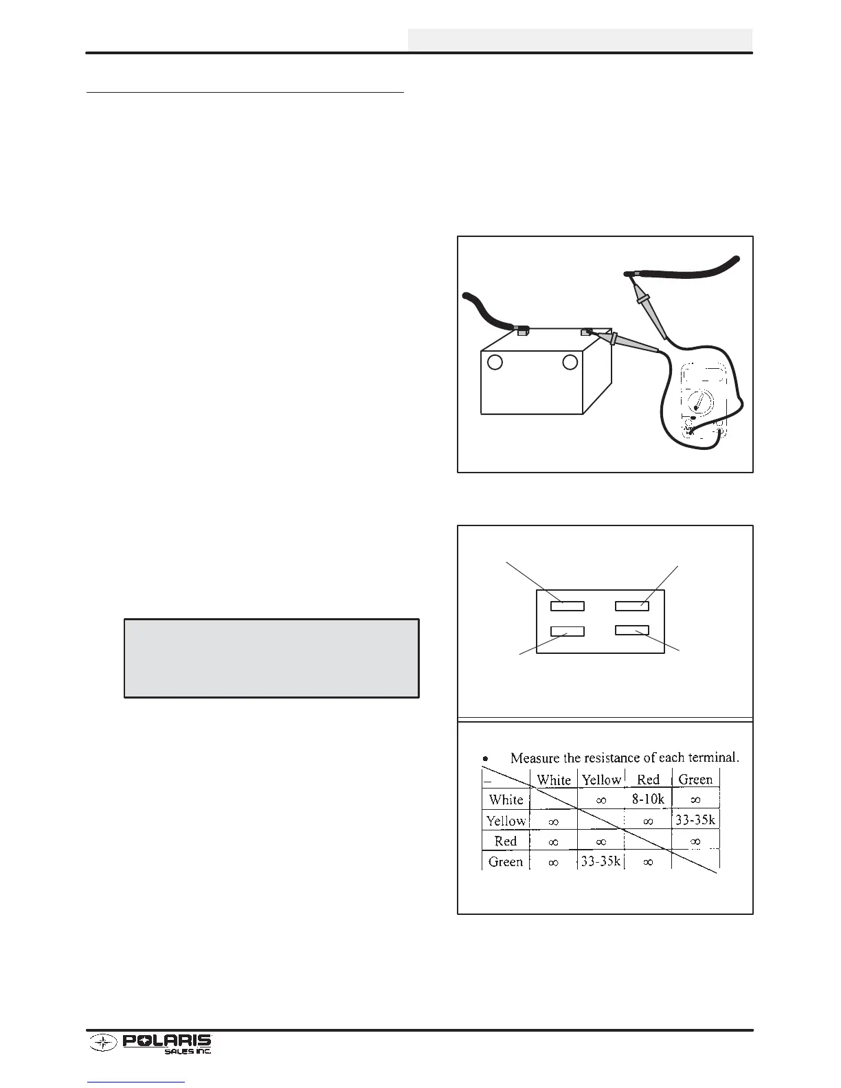
2. If the values do not meet the requirements, inspect the
regulator/rectifier. Measure the resistance of each
terminal and compare to chart at right. If any readings
are different than shown, replace regulator/rectifier.
Do not use electric start.
–+
Current Drain Inspection
Key Off
Less Than 9 mA
Red
White
Yellow
Green
Regulator Rectifier
Voltage: 13.5-15.5 V
Amperage: 1.0 A under 5000 RPM
 Loading...