SUSPENSION AND STEERING 2 - 5
November 2007 GEM Service Manual
FRONT SUSPENSION
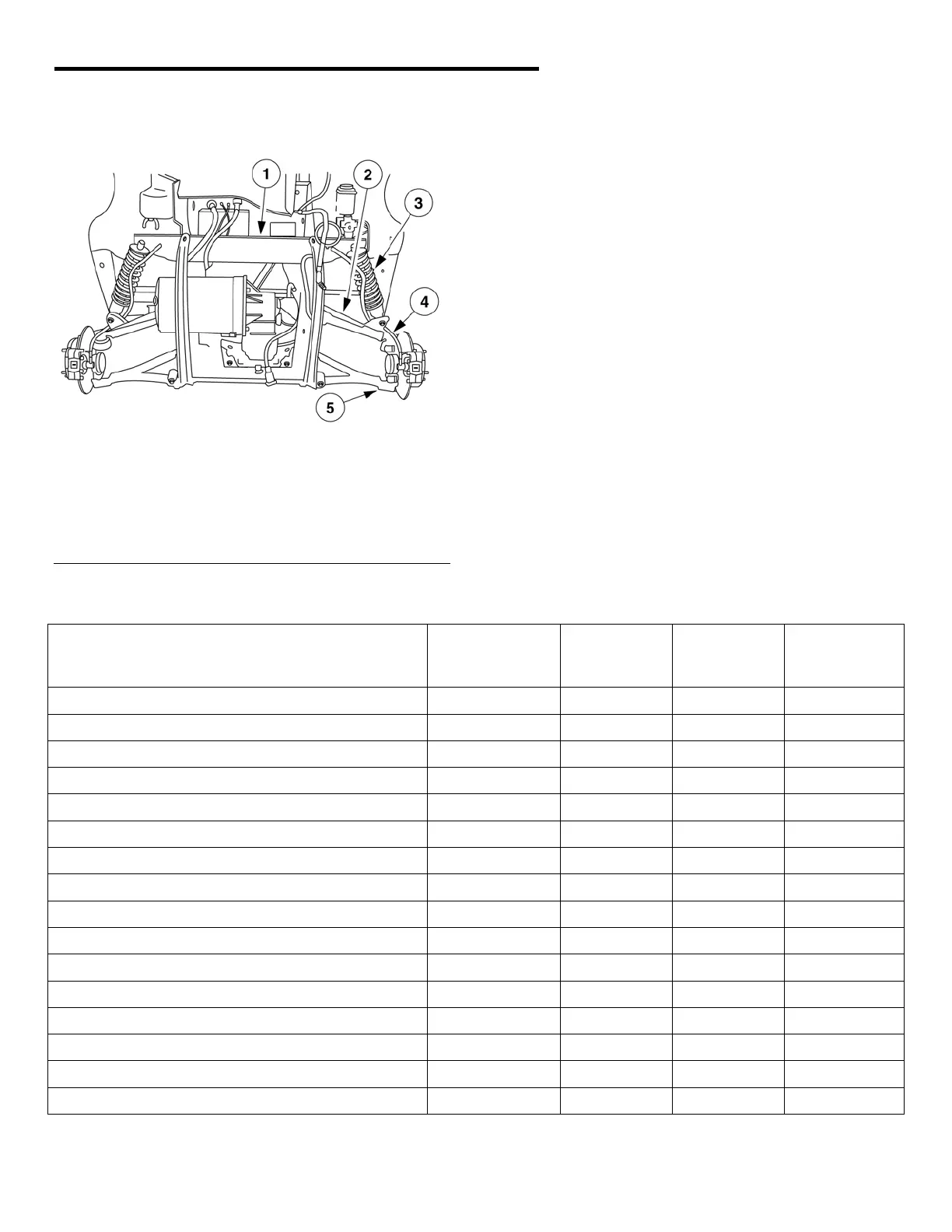
Fig. 5 Front Suspension System
1 - Front suspension frame
2 - Upper control arm
3 - Spring/shock absorber
4 - Knuckle
5 - Lower control arm
DESCRIPTION
The front suspension is designed to allow each
wheel to adapt to different road surfaces
independently. The wheels are mounted to rotor
assemblies, which in turn are mounted to the
steering components attached to a control arm, that
pivot up and down on bushings. Spring and shock
absorber assemblies at each yoke provide
cushioning.
CAUTION: Suspension components with
rubber/urethane bushings should be tightened
with the vehicle at normal ride height. It is
important to have the springs supporting the
weight of the vehicle when the fasteners are
tightened. This will maintain vehicle ride
comfort and prevent premature bushing wear.
TORQUE SPECIFICATIONS
Description Thread Size Use
Loctite®
242
Inch-
Pounds
Foot -
Pounds
Brake line to wheel/master cylinder
NO 37 ---
Control arm to frt. Suspension frame
M10 x 1.5 NO --- 30
Differential to frt. Suspension frame
5/16” –18 NO 225 ---
Front suspension frame to frame (lower)
M12 x 1.75 YES --- 40
Front suspension frame to frame (upper)
3/8 –16 YES --- 30
Halfshaft to knuckle assembly
M16 x 1.5 YES --- 65
Ball joint pinch bolt
M10 x 1.50 YES --- 30
Rack & Pinion to frt. Suspension frame
M8 x 1.25 NO 225 ---
Rear suspension frame to frame
M12 x 1.75 NO --- 60
Shock absorber lower bolt
M12 x 1.75 NO --- 60
Shock absorber upper bolt
M12 x 1.75 NO --- 60
Steering column pinch bolt
3/8 – 16 NO --- 35
Steering column to dash frame
5/16 – 18 NO 225 ---
Steering wheel to steering shaft
NO --- 20
Tie rod stud nut
M10 x 1.5 NO --- 35
Wheel lug nuts
12mm NO --- 65
 Loading...