Page 45 of 68
Proton Products InteliSENS PD30 Instruction Manual (Issue 1a)
STANDARD ELECTRICAL INTERFACES
SPEED PULSE INPUT
The speed pulse input may be connected to a line speed gauge (such as a Proton Products SL or
SLR series non-contact laser speed and length gauge).
Measured line speed input is required for:
Helix mode operation.
PI feedback controller operation.
Statistical Process Control (SPC) operation.
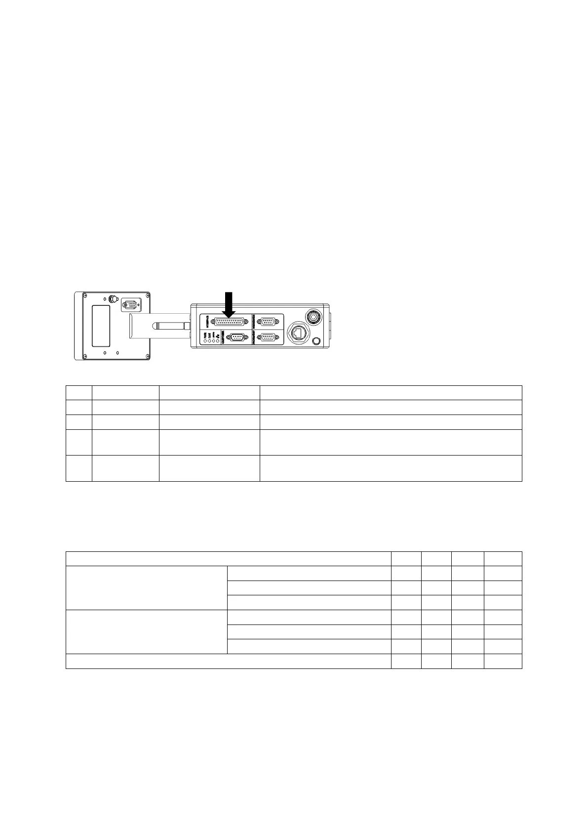
Speed pulse input connection
The speed pulse input is fitted as standard and may be accessed through the “INTERFACE”
connector.
Connector type: DB25 female (socket)
Ground reference for SPD1 and SPD2.
For low voltage speed pulses (e.g. 5V TTL).
For high voltage speed pulses
(e.g. 12 ~ 24V speed encoders).
Ensure that the cable shield is connected to this via the
plug shield connection.
Speed pulse input electrical specification
A choice of two speed pulse inputs are available: one input is for high voltage pulses and one
input is for low voltage pulses; only one input should be selected for use.
The ground reference (GND) for the speed pulse inputs is not isolated from earth.
SPD1 (pin13)
High voltage
(e.g. 12 ~ 24V speed encoders)
Low state (logic 0) input voltage
High state (logic 1) input voltage
SPD2 (pin 12)
Low voltage
(e.g. 5V TTL)
Low state (logic 0) input voltage
High state (logic 1) input voltage
 Loading...