Rins136 Issue 9 Page 17
8 POWER CONNECTIONS
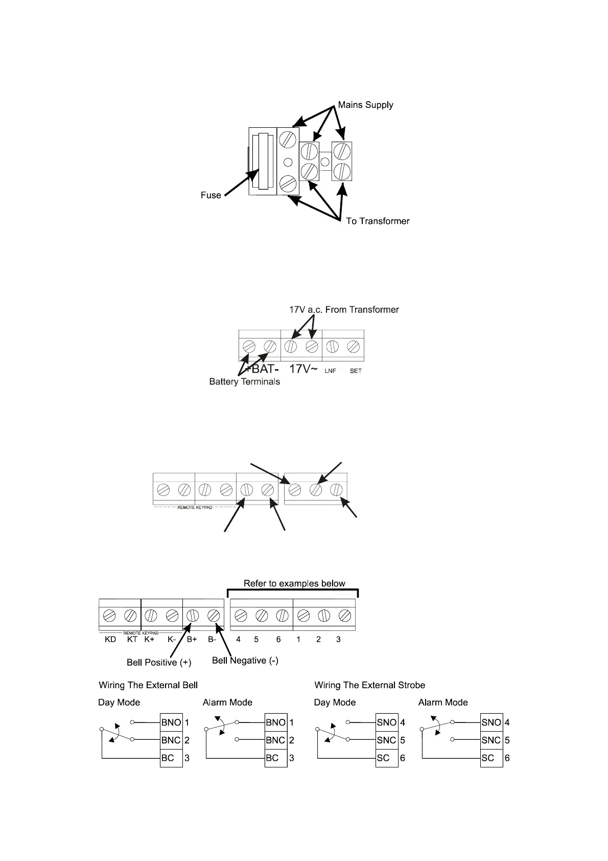
8.1 Mains Connections
The mains supply should be carefully wired to an a.c. mains supply using suitably rated 3 core cable with a current
capacity of not less than 5 amps. It should be connected to a fuse spur with a fuse rating of not more than 2 amps. The
mains connection at the power supply input are coded as follows, L – live, E – earth and N – neutral.
8.2 Battery Connection
In order for the Sterling 10 to operate if the mains power is cut a battery backup is required. Refer to 8.13 for battery
specifications. Connect the battery to the terminals marked +BAT- on the PCB.
8.3 Bell and Strobe (Transistor Version)
STB BA BTKD KT K+ K- B+ B-
Bell Positive (+)
Bell Negative (-)
Strobe - Switched Negative (-)
Bell Trigger - Switched Negative (-)
Bell Tamper
8.3.1 Bell and Strobe (Relay Version)
NOTE: The bell tamper BT connections should be wired in series to the dedicated tamper zone.
 Loading...