Rins136 Issue 9 Page 25
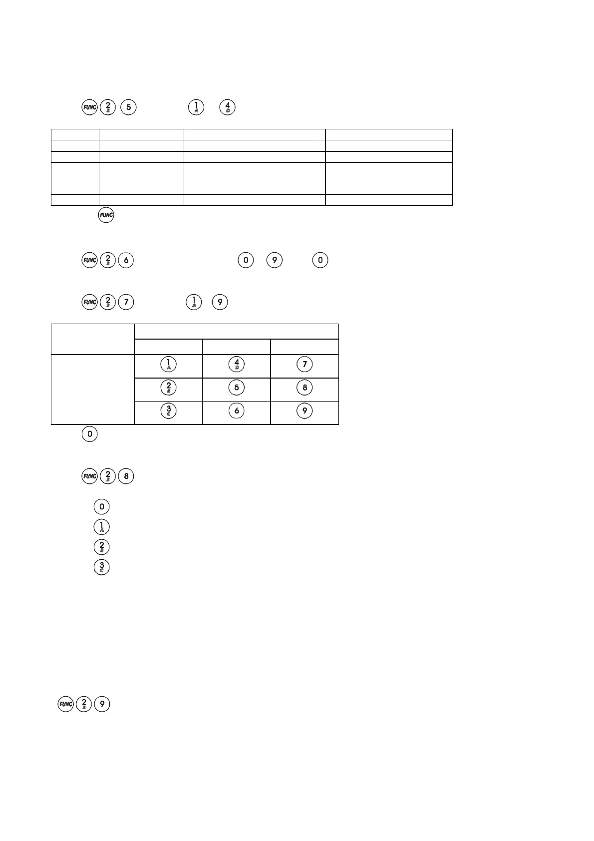
9.12.6 System Option 4.
Enter
followed by - to toggle RKP LEDs
Key Keypad LED LED ON LED OFF
1 Alarm Abort digi active high Abort digi active low
2 Tamper Open digi active high Open active low
3 P.A. Service timer warning and
lockout system on expire
Service timer warning on
expire if programmed with
function 27
4 Fire Anti-code reset enabled Anti-code reset disabled
Press the key to accept changes.
9.12.7 Programmable Re-sets
Enter
followed by a single digit - ( = continuous re-setting)
9.12.8 Service Timer
Enter
followed by - for the following Set/Unset cycles between service intervals.
Set/Unset Cycles Time Between Services
Per Day 30 Days 6 Months 12 Months
2
4
6
Enter for no service timer.
9.13 Keyswitch Set Configuration
Enter Enter a digit between 0 - 3.
Set A
Set B
Set C
Set D
9.14 Resetting the Non Volatile Memory (NVM) to Factory Settings
The panel may be programmed as Power up NVM reset or engineer code lock NVM reset.
Power Up NVM Reset
If the panel is configured by the engineer to allow the Power up to reset the NVM back to factory settings.
Locate the NVM reset pins on the PCB, using the link pin provided connect the two pins together. Power down the
system (mains and battery). Restore power and remove the link. The system is now back to factory default settings.
Engineer Code Lock NVM Reset
Enter the engineer mode. Open the panel cover, use the link supplied to connect the NVM reset pins together and enter
on the key pad. The system should bleep three times. The system is now back to factory default settings.
 Loading...