Rins136 Issue 9 Page 21
8.13 Battery Capacity
It is recommended that the rechargeable battery used with the Sterling 10 control panel should be capable of powering
the alarm system for a minimum of 8 hours, and that this time period should include 20 minutes of bell/strobe operation.
The minimum battery capacity should be calculated from the current consumption of the individual system components.
A typical example based on the following individual parts is shown below:
Non alarm current for control panel (7hrs 40min) : 130mA (0.130 A)
Steady state current for detectors : 120mA (0.120 A)
(e.g. 8 x 15mA for 8 hours - Pyronix PIRs)
Typical stand-by current for external sounder : 50mA (0.050 A)
(e.g. Self Actuating Bell for 8 hours)
Typical on state current for external sounder (20 mins) : 350mA (0.35 A)
Alarm state current for control panel (20 mins) : 130mA (0.13 A)
Typical current for external strobe (8 hours) : 150mA (0.15 A)
Alarm condition for 20 mins (0.333 hrs)
Alarm state current for control panel : 0.130
8 detectors @15mA each : 0.120
External sounder : 0.350
External strobe : 0.150
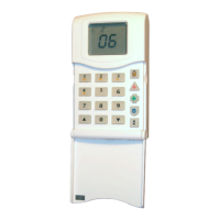
Single remote keypad : 0.015
Required capacity for alarm condition = 0.765 x 0.333 = 0.255 Ahrs
Capacity required for stand-by 7hrs 40 mins (7.67 hrs)
Non alarm current for control panel : 0.130
8 detectors @ 15mA each : 0.120
External strobe : 0.150
Stand-by for external sounder : 0.050
Single Remote keypad : 0.015
Required capacity for stand-by condition = 0.465 x 7.67 = 3.57 Ahrs
Total minimum required battery capacity = 0.255 + 3.57 = 3.825 Ahrs
For this example it is recommended that you use a battery of not less than 7 AH.
8.14 Powering Up Your Panel / RKP.
a. Connect the battery leads to the control panel. (+BAT-). The red lead should be connected to "+" (positive)
terminal and the black lead to "-" (negative) terminal.
b. Connect the battery. The red lead should be connected to "+" (positive) terminal and the black lead to "-"
(negative) terminal.
c. Switch on the AC supply. The supply LED will be on. Now proceed to section 9 "Programming".
 Loading...