NB-IoT Module Series
BC95 Hardware Design
BC95_Hardware_Design Confidential / Released 19 / 51
2, 43, 47, 48, 51, 52,
54, 59~66, 71~74,
81~83, 92~94
3.5.2. Reference Design for Power Supply
The power design for the module is very important, as the performance of the module largely depends on
the power source. A Low quiescent current LDO which can provide sufficient input current up to 0.5A can
be used as the power supply. Meanwhile, Li-SOCI2 batteries can also be used to supply power for the
module. The power supply range of the module is from 3.1V to 4.2V. Please make sure that the input
voltage will never drop below 3.1V even in burst transmission. If the power voltage drops below 3.1V, the
module will be abnormal.
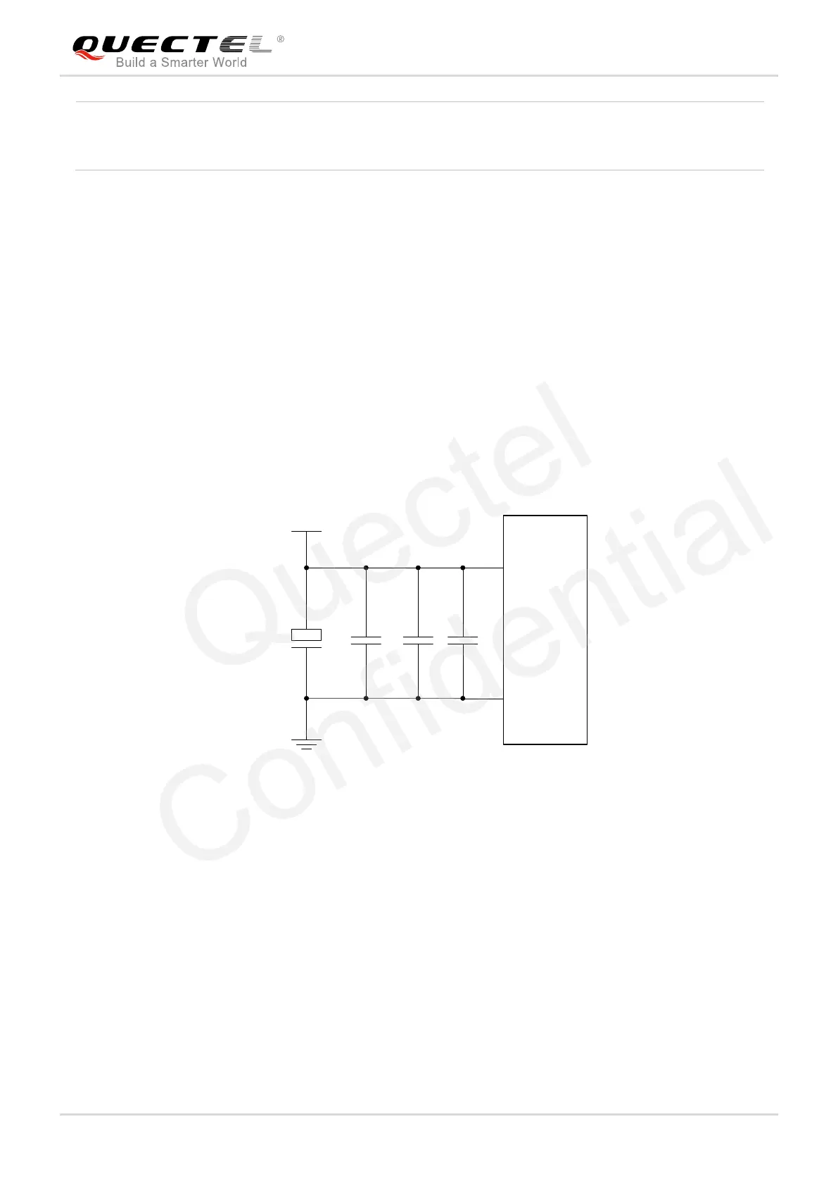
For better power performance, it is recommended to place a 100uF tantalum capacitor with low ESR
(ESR=0.7Ω) and three ceramic capacitors with 100nF, 100pF and 22pF near the VBAT pin. A reference
circuit is illustrated in the following figure. In principle, the longer the VBAT trace is, the wider it will be.
VBAT
C2C1
+
C3 C4
GND
100uF 100nF 100pF 22pF
0402 0402
VBAT
Module
GND
Figure 3: Reference Circuit for the VBAT Input
3.6. Power on and down Scenarios
3.6.1. Power on
The module can be automatically turned on by supplying power source to VBAT pins.

 Loading...


