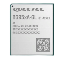
LPWA Module Series
BG950A-GL&BG951A-GL_Hardware_Design
5
/89
Contents
Safety Information......................................................................................................................................................3
About the Document..................................................................................................................................................4
Contents........................................................................................................................................................................5
Table Index................................................................................................................................................................... 7
Figure Index................................................................................................................................................................. 9
1 Introduction....................................................................................................................................................... 10
1.1. Special Mark..........................................................................................................................................13
2 Product Overview.............................................................................................................................................14
2.1. Frequency Bands and Functions.......................................................................................................15
2.2. Key Features.........................................................................................................................................16
2.3. Functional Diagram..............................................................................................................................18
2.4. Pin Assignment..................................................................................................................................... 19
2.5. Pin Description......................................................................................................................................20
2.6. Evaluation Board.................................................................................................................................. 26
3 Operating Characteristics..............................................................................................................................27
3.1. Operating Modes..................................................................................................................................27
3.2. Sleep Mode*..........................................................................................................................................28
3.2.1. UART Application Scenario...................................................................................................... 28
3.3. Power Saving Mode (PSM)*...............................................................................................................29
3.4. Extended Idle Mode DRX (e-I-DRX).................................................................................................29
3.5. Airplane Mode.......................................................................................................................................30
3.6. Power Supply........................................................................................................................................31
3.6.1. Power Supply Pins.....................................................................................................................31
3.6.2. Power Supply Monitoring..........................................................................................................31
3.6.3. Requirements for Voltage Stability..........................................................................................31
3.7. Turn On.................................................................................................................................................. 33
3.7.1. Turn on the Module with PWRKEY*....................................................................................... 33
3.8. Turn Off.................................................................................................................................................. 34
3.8.1. Turn off the Module with PWRKEY*........................................................................................34
3.8.2. Turn off the Module with AT Command.................................................................................. 35
3.9. Reset...................................................................................................................................................... 35
3.10. PON_TRIG*...........................................................................................................................................37
4 Application Interfaces.....................................................................................................................................39
4.1. (U)SIM Interface................................................................................................................................... 39
4.2. USB Interface*...................................................................................................................................... 41
4.3. PCM and I2C Interfaces*.................................................................................................................... 43
4.4. UART Interfaces................................................................................................................................... 44
4.5. ADC Interface........................................................................................................................................46
4.6. Indication Signal................................................................................................................................... 47

 Loading...