EasyManuals Logo
Home>Raisecom>Remote Control>ISCOM RAX711

Raisecom ISCOM RAX711 User Manual

Raisecom ISCOM RAX711
67 pages
To Next Page IconTo Next Page
To Previous Page IconTo Previous Page
Page #53 background imageLoading...
Page #53 background image
Raisecom
ISCOM RAX711 (B)Product Description
Raisecom Technology Co., Ltd.
43
Table 6-9 lists PIN definitions on the serial interface on the PC.
Table 6-9 PIN definitions on serial interface on PC
PIN
Definition
PIN
Definition
PIN 1
DCD
PIN 6
DSR
PIN 2
RxD
PIN 7
RTS
PIN 3
TxD
PIN 8
CTS
PIN 4
DTR
PIN 9
RI
PIN 5
GND
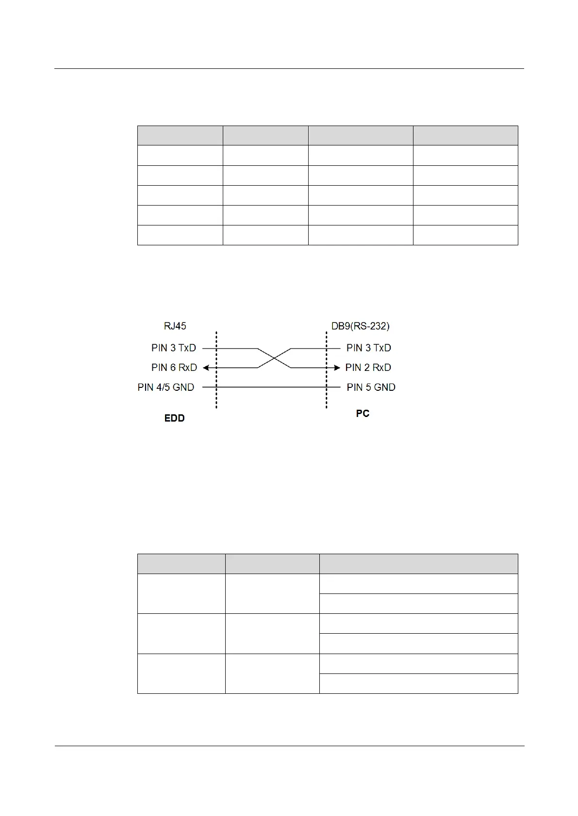
Figure 6-7 shows the wiring between PINs on the ISCOM RAX711 and PINs on the PC.
Figure 6-7 Wiring between PINs on device and PINs on PC
6.1.5 Fiber
Introduction
The ISCOM RAX711 supports single-mode and multi-mode fiber.
Table 6-10 lists fiber connectors available for the ISCOM RAX711.
Table 6-10 Fiber connectors
Local connector
Remote connector
Fiber
LC/PC
LC/PC
2 mm single-mode fiber
2 mm multi-mode fiber
LC/PC
FC/PC
2 mm single-mode fiber
2 mm multi-mode fiber
LC/PC
SC/PC
2 mm single-mode fiber
2 mm multi-mode fiber

Table of Contents

Questions and Answers:

Question and Answer IconNeed help?

Do you have a question about the Raisecom ISCOM RAX711 and is the answer not in the manual?

Raisecom ISCOM RAX711 Specifications

General IconGeneral
BrandRaisecom
ModelISCOM RAX711
CategoryRemote Control
LanguageEnglish