20
APPENDIX 1
RIM DRILLING INSTRUCTIONS FOR WHEEL DRIVE SPEED
SENSOR MAGNETS
On wheels which do not have pre-punched mounting holes, proceed as follows:
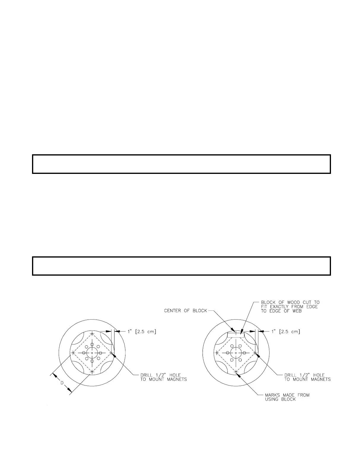
RIMS WITH FOUR OR EIGHT HOLE STUD PATTERN:
Choose stud holes that are opposite each other as shown in Figure 8. Using the
center of opposite holes, scribe two lines on the rim web to divide the
circumference into four equal parts. Measure in one inch from the outer edge of
the web on each of the lines drawn. Mark this point as the center. Drill four
1/2" holes for mounting the magnets.
NOTE: Distance (D) between each set of drilled holes must be equal within 1/8"
[3 mm] to ensure accuracy of system.
RIMS WITH SIX HOLE STUD PATTERN:
Locate the center of the holes to be drilled by using the rim webbing as a guide.
(See Figure 9). Obtain a small piece of wood and cut to fit exactly over the web
as shown in Figure 9. Measure the length of the piece of wood and mark the center
on one edge. Using the center mark on the piece of wood, mark each of the four
webs. Measure in one inch from the outer edge of the web on each of the lines
drawn. Mark this point as center and drill four 1/2" holes for mounting the
magnets.
NOTE: Distance (D) between each set of drilled holes must be equal within l/8"
[3 mm] to ensure accuracy of system.
FIGURE 9
SIX HOLE STUD PATTERN
FIGURE 8
EIGHT HOLE STUD PATTERN
 Loading...