21
APPENDIX 2
PROCEDURE TO TEST SPEED SENSOR EXTENSION CABLES
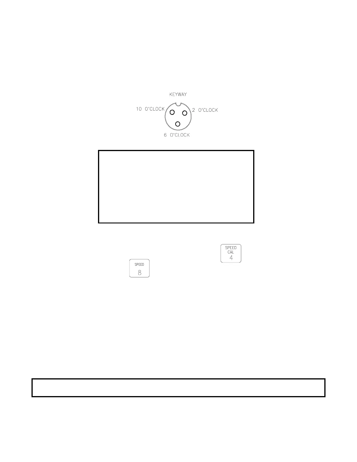
Disconnect extension cable from Speed Sensor Assembly cable. Hold extension cable
connector so that keyway is pointing in the 12 o’clock position.
1) 2 o’clock socket is power.
2) 10 o’clock socket is ground.
3) 6 o’clock socket is signal.
VOLTAGE READINGS
1) 10 o’clock to 6 o’clock (+5 VDC).
2) 10 o’clock to 2 o’clock (+5 VDC).
Procedure to check cable:
l) Enter SPEED CAL number of 1000 in key labelled:
2) Depress key labelled:
3) With small jumper wire (or paper clip), short between 10 o’clock and 6 o’clock
sockets with a "short-no short" motion. This should cause a speed reading to
be displayed in the Console. Each time a contact is made, the DISTANCE total
should increment up 1 or more counts.
4) If DISTANCE does not count up, remove the section of cable and repeat test at
connector next closest to Console. Replace defective cable as required.
5) Perform above voltage checks.
6) If all cables test good, replace speed sensor.
NOTE: After testing is complete, re-enter correct SPEED CAL number before
application.
 Loading...