18
2 USER GUIDE
2.2.1 Remote Port (RJ11)
The RS Series inverter can be used with the REMOTE-RS remote controls via RS-232 communication.
To enable, set the main switch on the inverter to the REMOTE position.
Pin Number Signal Description (1)
1 Reserved --
2 GND Same Polarity as Battery Negative
3 RXD RS232 RXD
4 TXD RS232 TXD
5 RMT Remote controller panel (positive)
6 VCC Internal power for remote controller
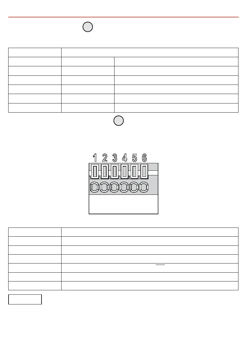
2.2.2 Remote Control Green Terminal
The remote control green terminal is connected to a Form C relay for fault indication. When a fault occurs,
the relay switches. Fault conditions include Input Under/Over voltage, output short-circuit/overload, Under/
Over temperature.
FIGURE 2.2.2.1: Remote Control Terminal
Pin Number Terminal Description
1 Fault relay, Normally Open (16V, 10mA max.)
2 Fault relay, Common (16V, 10mA max.)
3 Fault relay, Normal Closed (16V, 10mA max.)
4 Enable+ (ENB
)
5 Enable− (ENB)
6 Ground (Same polarity as battery negative)
NOTICE
• Before Installing — Make sure that the inverter main switch is at OFF position
• Before using the remote function, make sure the main switch is set to 'REMOTE'
• Use 20 to 24AWG cable to connect the remote control terminals
1
2
 Loading...