19
2 USER GUIDE
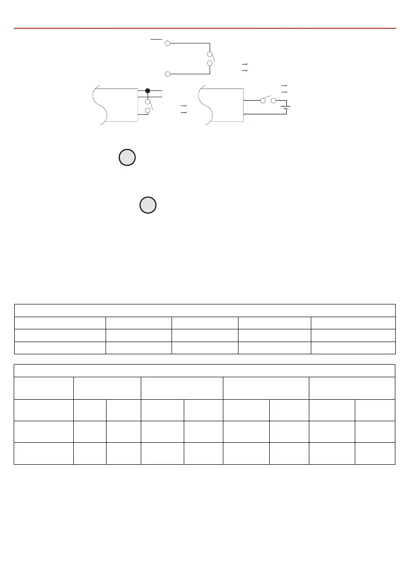
ENB
GND
GND
BAT+
BAT–
ENB
ENB
ON:INV.
OFF:INV.
ON
OFF
ON:INV.
OFF:INV.
ON
OFF
+ DC
– POWER
ON:INV.
OFF:INV.
ON
OFF
FIGURE 2.2.2.2: Wiring configurations for Remote Control Green Terminal
2.2.3 Chassis Ground
Use 16 AWG (1.5mm²) or a thicker cable to connect the vehicle earth or chassis ground. Perform this
connection prior to any other connection.
2.2.4 DC Input Connection
Prior to installation:
• The cable and fuse sizes in Table 2.2.4.1 are recommended for connection between supply battery
and inverter. The DC supply cables should be as short as possible and no longer than the values
shown in Table 2.2.4.1.
• The size of the cable should be thick enough to maintain a voltage drop of less than 2% when
carrying the maximum input current. This will help prevent frequent low-input voltage warnings and
shutdown.
TABLE 2.2.4.1: Recommended Fuse and Cable Sizing (12V Install):
Recommended Fuse size
12V Inverter 1000W 1500W 2000W 3000W
Fuse Size 175A 225A 250A 450A
Recommended Fuse Mega Mega Mega Mega
Recommended Cable size AWG (nearest equivalent in mm
2
)
Cable length
ft (m)
1000W 1500W 2000W 3000W
0–6.6
(0−2)
0 (1/0)
54mm
2
000 (3/0)
85mm
2
0000 (4/0)*
105mm
2
0000 (4/0)*
120mm
2
6.6–9.8
(2−3)
00 (2/0)
68mm
2
000 (3/0)
85mm
2
0000 (4/0)*
105mm
2
/
9.8–13.1
(3−4)
/ 0000 (4/0)
105mm
2
0000 (4/0)*
120mm
2
/
Fuse ratings are suitable for these recommended minimum cable sizes.
High temperature (230°F/110°C) or higher rated cable is required.
3
4
 Loading...