Renesas RA Family EK-RA6M5 v1 – User's Manual
R20UT4829EG0100 Rev. 1.00 Page 20 of 34
Mar.15.21
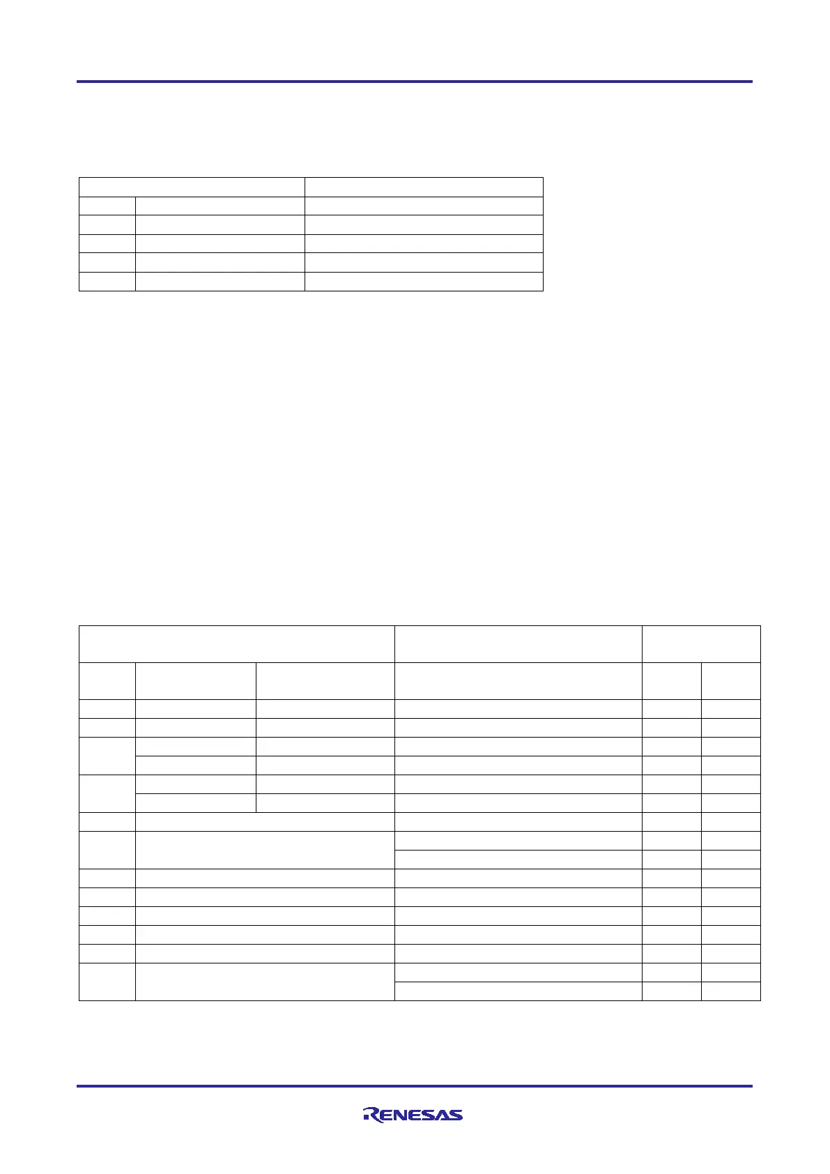
5.3.2 SparkFun
®
Qwiic Connector
A SparkFun
®
Qwiic connector is provided at J30. The Main MCU acts as a two-wire serial master, and a
connected module acts as a two-wire serial slave. (Data lines shared with Grove 1.)
Table 12. Qwiic Connector
5.3.3 Digilent Pmod™
Connectors
Two 12-pin connectors are provided to support Pmod modules where the RA MCU acts as the master, and
the connected module acts as a slave device.
These interfaces may be configured in firmware to support several Pmod types such as Type-2A (expanded
SPI) and Type-3A (expanded UART).
The EK-RA6M5 board also provides jumpers so the 12-pin connector may alternatively be used for 2
independent 6-pin Pmod devices where the top row supports Pmod Type-2 (SPI) and Type-3 (UART) while
the bottom row supports Pmod Type-6 (I
2
C).
The default 12-pin Pmod interface supports +3.3 V devices. Please ensure that any Pmod device installed is
compatible with a +3.3 V supply.
The 6-pin Pmod interface option for Type-6 (I2C) may also support +5.0 V devices. Please ensure that only
6-pin modules are used when this option is selected.
5.3.3.1 Pmod 1
A 12-pin Pmod connector is provided at J26, Pmod 1.
Table 13. Pmod 1 Connector
Signal/Bus
GPIO / INT (slave to master)
GPIO / RESET (master to slave)
Note: Exercise caution while modifying power source trace jumpers, E25 and E36. Permanent
damage to the EK-RA6M5 board and/or connected modules may result.

 Loading...


