RZ Family / RZ/G, RZ/A Series 2. Functional Specifications
R01UH0990EJ0101 Rev.1.01 Page 56 of 83
Jul 28, 2022
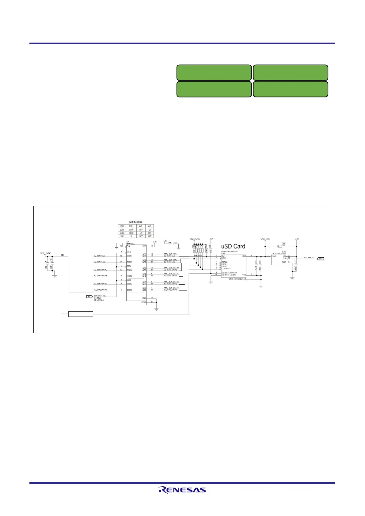
2.11.2 SD Card
Figure 2.14 shows a block diagram of the SD0 interface.
The microSD card is connected to channel 0 of SD/MMC interface that is with built-in to the RZ/G2UL. This memory
is used in conjunction with eMMC memory.
The microSD card may be used when
●
the microSD is the selected boot mode (SW11-1: ON, SW11-2: ON, SW11-3: OFF)
●
the SW_SD0_DEV_SEL is disabled (SW1-2: Selection SD/MMC is ON) and eMMC memory is not the selected
boot mode (SW11-1: ON, SW11-2: OFF, SW11-3: OFF).
This interface complies with the memory card standard version 3.0 and supports UHS-I mode of 50MB/s (SDR50) and
104MB/s (SDR104).
Figure 2.14 Block Diagram of SD0 I/F
SD0_CLK
SD0_CMD
SD0_DATA0
SD0_DATA1
SD0_DATA2
SD0_DATA3
SD0_PVDD
SD0_CD
SD0_PVDD
RZ/G2UL, RZ/A3UL, RZ/Five
RZ/G2UL, RZ/A3UL, RZ/Five

 Loading...


