RZ Family / RZ/G, RZ/A Series 2. Functional Specifications
R01UH0990EJ0101 Rev.1.01 Page 57 of 83
Jul 28, 2022
2.12 GreenPAK
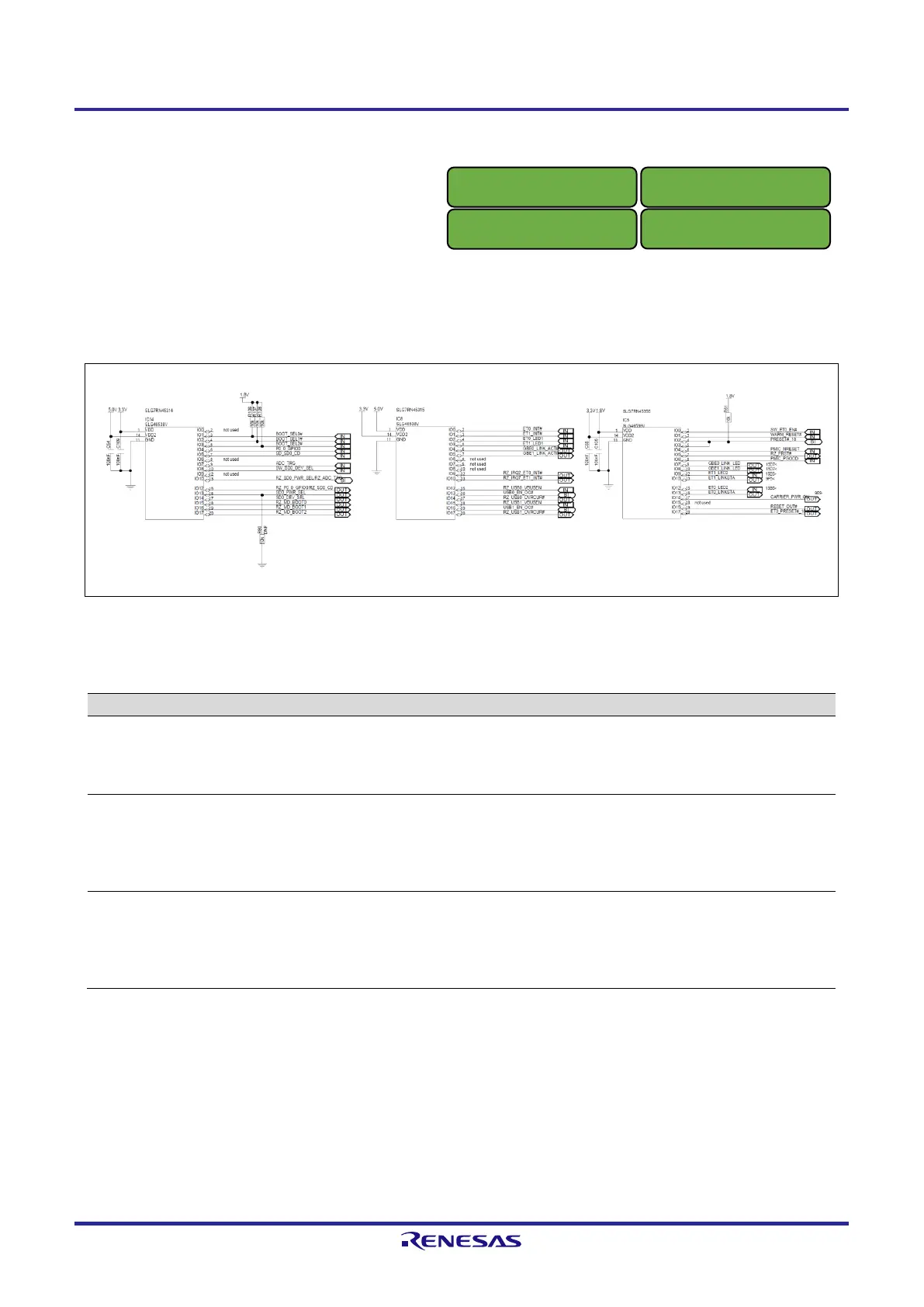
Figure 2.15 shows a block diagram of the GreenPAK.
This board is implemented several types of the GreenPAK with integrated various peripheral functions. Table 2.3
shows a function of the each GreenPAK used with this board.
Figure 2.15 Block Diagram of Each GreenPAK
Table 2.3 Features of Each GreenPAK
SMARC Boot Mode
SD0_CD / GPIO4 multiplexing
SD0_PWR_SEL / ADC_TRG multiplexing
SD0_DEV_SEL (microSD card or eMMC)
USB0/1
Logic for EN_OC#
Etehnet0/1
Logic for interrupt level shifting
LINK Active LED drive
Reset Logic
SMARC Carrier Power ON
Ethernet0/1
LINK LED drive
LINK status inversion
The pin configuration and of each GreenPAK is described in the next section. Please refer to the following data sheet
included with the design data in detail.
●
SLG7RN45314_DS_r014_12152021.pdf
●
SLG7RN45315_DS_r011_10292021.pdf
●
SLG7RN45356_DS_r010_11012021.pdf
RZ/A3UL SMARC Module Board
OCTAL Edition
RZ/A3UL SMARC Module Board
QSPI Edition
RZ/G2UL SMARC Module Board
RZ/Five SMARC Module Board

 Loading...


