Renesas Starter Kit+ for RZ/T2M 3. Board Layout
R20UT4939EG0100 Rev. 1.00 Page 12 of 87
Apr 20, 2022
3. Board Layout
3.1 Component Layout
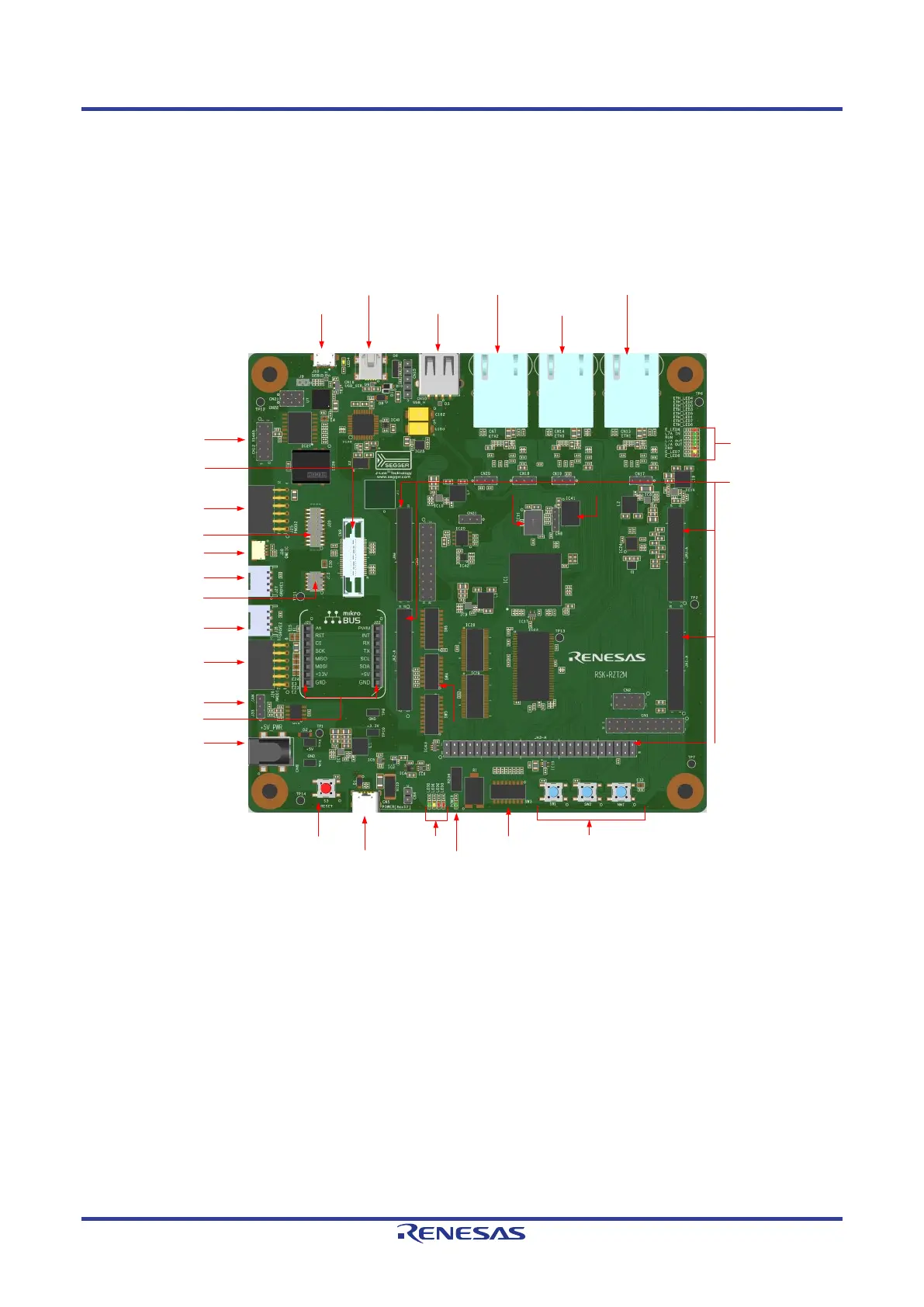
Figure 3-1, Figure 3-3 below shows the top component layout of the board.
PMOD
TM
(UART)
Connector
QWIIC
®
Compatible Connector
Grove
®
(I
2
C)
Connector
Grove
®
(Analog)
Connector
PMOD
TM
(SPI)
Connector
DC PWR IN
(5V, Adapter)
CAN Connector
mikroBUS
TM
Connectors
RS485
Connector
External Debugger(MIPI-10)
Connector
External Debugger(MIPI-20)
Connector
External Debugger(Mictor
-38)
Connector
EtherCAT LEDs
Application Board Interface
(Application Headers)
SDRAM
Octa Flash Hyper RAM
MODE DIP Switch
RESET Switch
DC PWR IN
(5V, USB Type-C)
Use r LEDs
Power LED(5V)
User Switches
User DIP Switch
J-Link® OB
USB Connector
USB to Serial Port
USB Connector
USB HOST
Connector
Ethernet(ETH2)
Connector
Ethernet(ETH0)
Connector
Ethernet(ETH1)
Connector
Figure 3-1: Board Layout (Top side)
 Loading...


