Renesas Starter Kit+ for RZ/T2M 6. Configuration
R20UT4939EG0100 Rev. 1.00 Page 72 of 87
Apr 20, 2022
6.29 Serial & RS485 Configuration
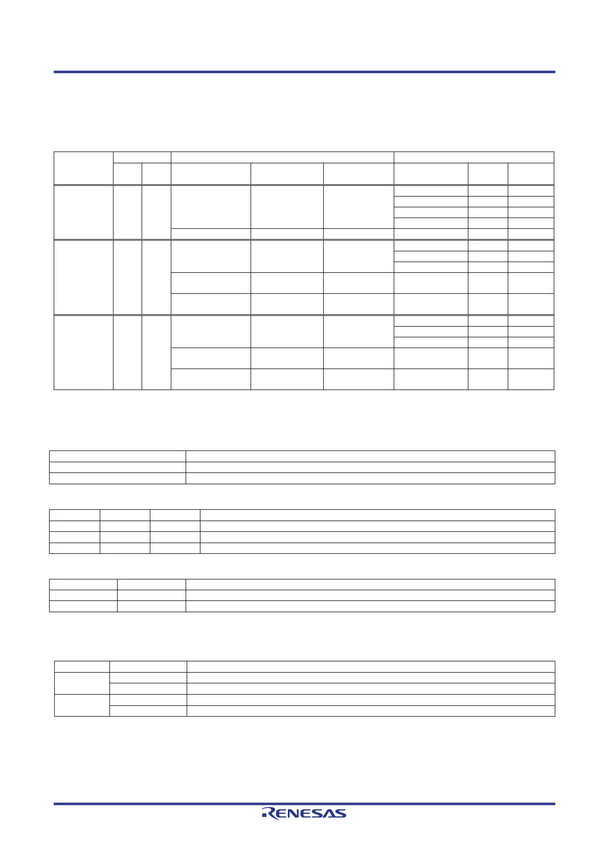
Table 6-90 below details the function of the option links associated with Serial & RS485 Configuration.
Table 6-90: Serial & RS485 Configuration Option Links
Signal name
Pin
Port
Signal Fit DNF
Fit DNF
P18_0 H16 P18_0
SCI_TXD SW6-6 = ON SW6-5 = OFF
P17_7 G20 P17_7
SCI_RXD SW5-5 = ON
SW5-6 = OFF
SW5-7 = OFF
RS485_RXD SW5-6 = ON
IC27.3 - -
M1_VP SW5-7 = ON
JA2-A.15 - -
BSC_A07_MD0
RS485_DE
N1 P04_5
BSC_A07
IC29.47
(SW6-1 = ON)
-
RS485_DE
- IC27.5 - -
- - SW4.1 IC14.18 -
Table 6-91, Table 6-92, Table 6-93 below details the function of the switches associated with the Serial &
RS485.
Table 6-91: Serial & RS485 Configuration Switch Settings (1)
Enable the external bus signal.
Enables signals other than the external bus. (CAN, Emulator, I
2
C, etc.)
Table 6-92: Serial & RS485 Configuration Switch Settings (2)
Enable the "M1_VP" signal.
Enable the "RS485_RXD" signal.
Enable the "SCI_RXD" signal.
Table 6-93: Serial & RS485 Configuration Switch Settings (3)
Enable the "SCI_TXD" signal.
Enable the "M1_VN" signal.
Table 6-94 below details the function of the jumpers associated with the Serial & RS485.
Table 6-94: Serial & RS485 Configuration Jumper Settings
CN21
CN22
 Loading...


