Renesas Starter Kit+ for RZ/T2M 5. User Circuitry
R20UT4939EG0100 Rev. 1.00 Page 17 of 87
Apr 20, 2022
5. User Circuitry
5.1 Reset Circuit
A reset control circuit is fitted to the CPU board to generate the required reset signal and is triggered from the
RESET switch and the power-on-reset circuit. Refer to the RZ/T2M Group User’s Manual: Hardware for
details regarding the reset signal timing requirements, and the CPU board schematics for information
regarding the reset circuitry in use on the board.
5.2 Clock Circuit
A clock circuit is fitted to the CPU board to generate the required clock signal to drive the MPU, and
associated peripherals. Refer to the RZ/T2M Group Hardware Manual and the RL78/G1C hardware manual
for details regarding the clock signal requirements, and the CPU board schematics for information regarding
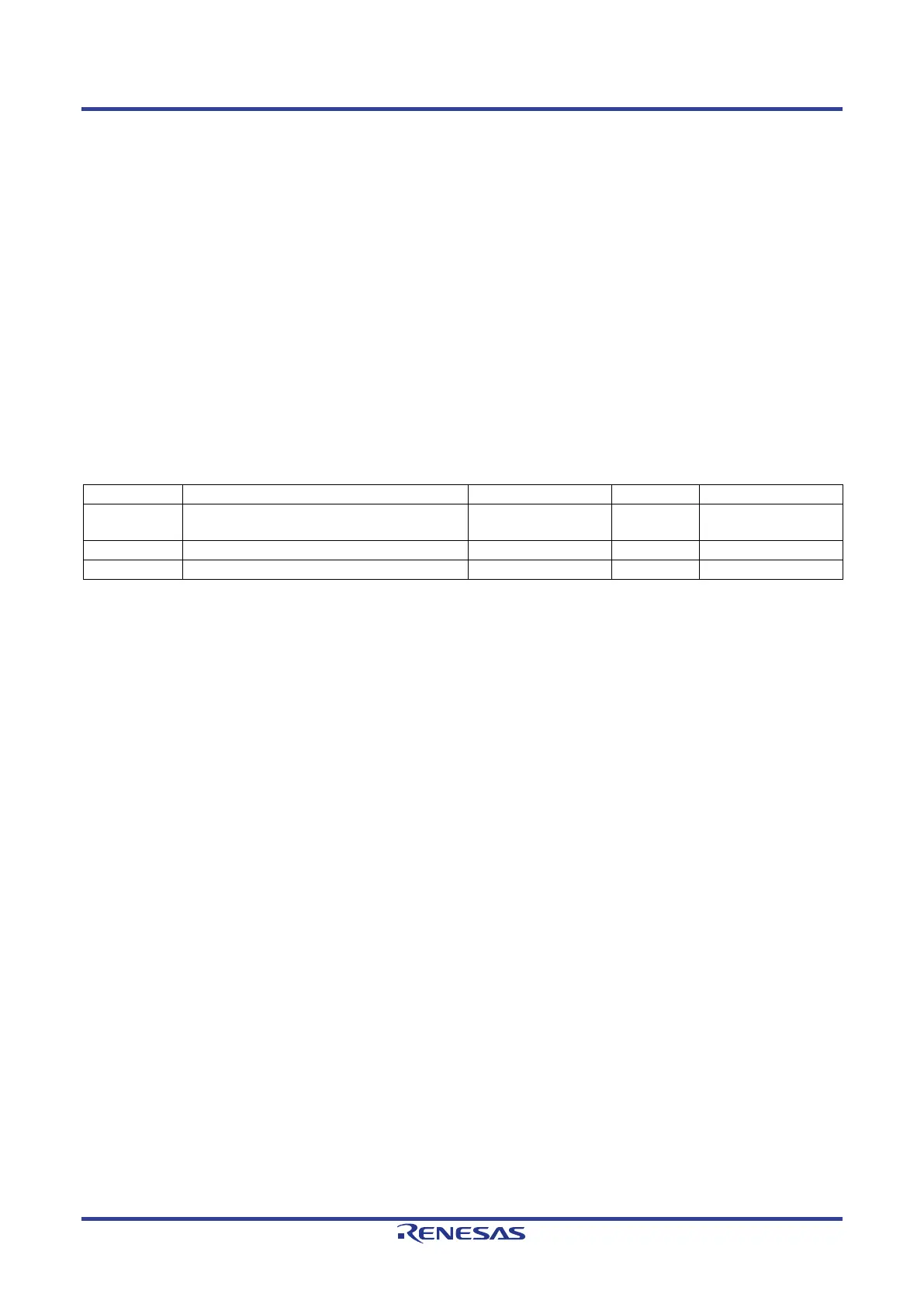
the clock circuitry in use on the CPU board. Details of the oscillators fitted to the board are listed in Table 5-1:
Crystal below.
Table 5-1: Crystal
X1
Main MPU crystal for RZ/T2M
(via clock generator (IC24))
Not fitted 25MHz Encapsulated, SMT
Main MCU crystal for RL78/G1C
Main MPU crystal for RZ/T2M (MPU direct)
 Loading...


