Renesas Starter Kit+ for RZ/T2M 5. User Circuitry
R20UT4939EG0100 Rev. 1.00 Page 29 of 87
Apr 20, 2022
5.15 Universal Serial Bus (USB)
This CPU board is fitted with a USB Host socket (type A, CN10) and a Function socket (type Mini B, CN11).
USB module is connected to the Host and Function socket and can operate as either a Host or Function
device. However, they cannot be used at the same time.
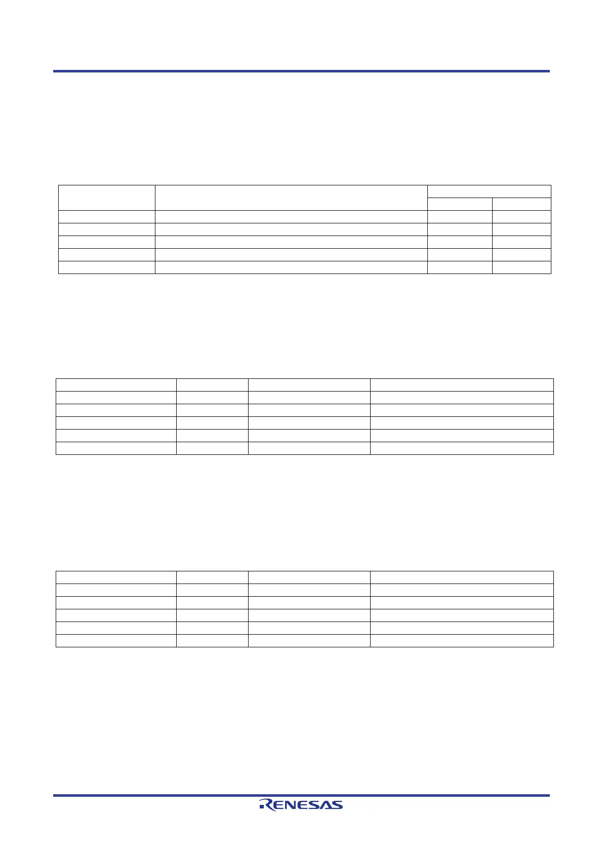
The connection for the USB module is shown in
Table 5-22 below.
Table 5-22: USB Module Connections
USB Signal Function
D+ I/O pin of the USB on-chip transceiver
D– I/O pin of the USB on-chip transceiver
VBUS (5V) supply enable signal for external power supply chip
Outputs the VBUS power enable signal for USB.
External overcurrent detection signal B
5.16 External Bus
The RZ/T2M features an external data bus, which is connected to various devices on the CPU board. Details
of the devices connected to the external data bus are listed in Table 5-23 below. Further details of the devices
connected to the external bus can be found in the board schematics.
Table 5-23: External Bus Address Space
70000000h – 71FFFFFFh (32Mbyte)
74000000h – 77FFFFFFh (64Mbyte)
78000000h – 79FFFFFFh (32Mbyte)
78000000h – 7BFFFFFFh (64Mbyte)
7C000000h – 7FFFFFFFh (64Mbyte)
5.17 Expanded Serial Peripheral Interface (xSPI)
The RZ/T2M features two Expanded Serial Peripheral Interface modules (xSPI). The extended serial
peripheral interface is connected to the device on the CPU board. Details of the devices connected to the
extended serial peripheral interface are shown in Table 5-24 below. Further details of the devices connected
to the extended serial peripheral interface can be found in the board schematics.
Table 5-24: Expanded Serial Interface (xSPI) Address Space
60000000h – 63FFFFFFh (64Mbyte)
60000000h – 63FFFFFFh (64Mbyte)
64000000h – 67FFFFFFh (64Mbyte)
68000000h – 687FFFFFh (8Mbyte)
6C000000h – 6FFFFFFFh (64Mbyte)
*1
: This connection is a not available in the default RSK+ configuration - refer to section 6 for the required
modifications.
 Loading...


