Renesas Starter Kit+ for RZ/T2M 4. Connectivity
R20UT4939EG0100 Rev. 1.00 Page 16 of 87
Apr 20, 2022
4.2 Emulator Connections
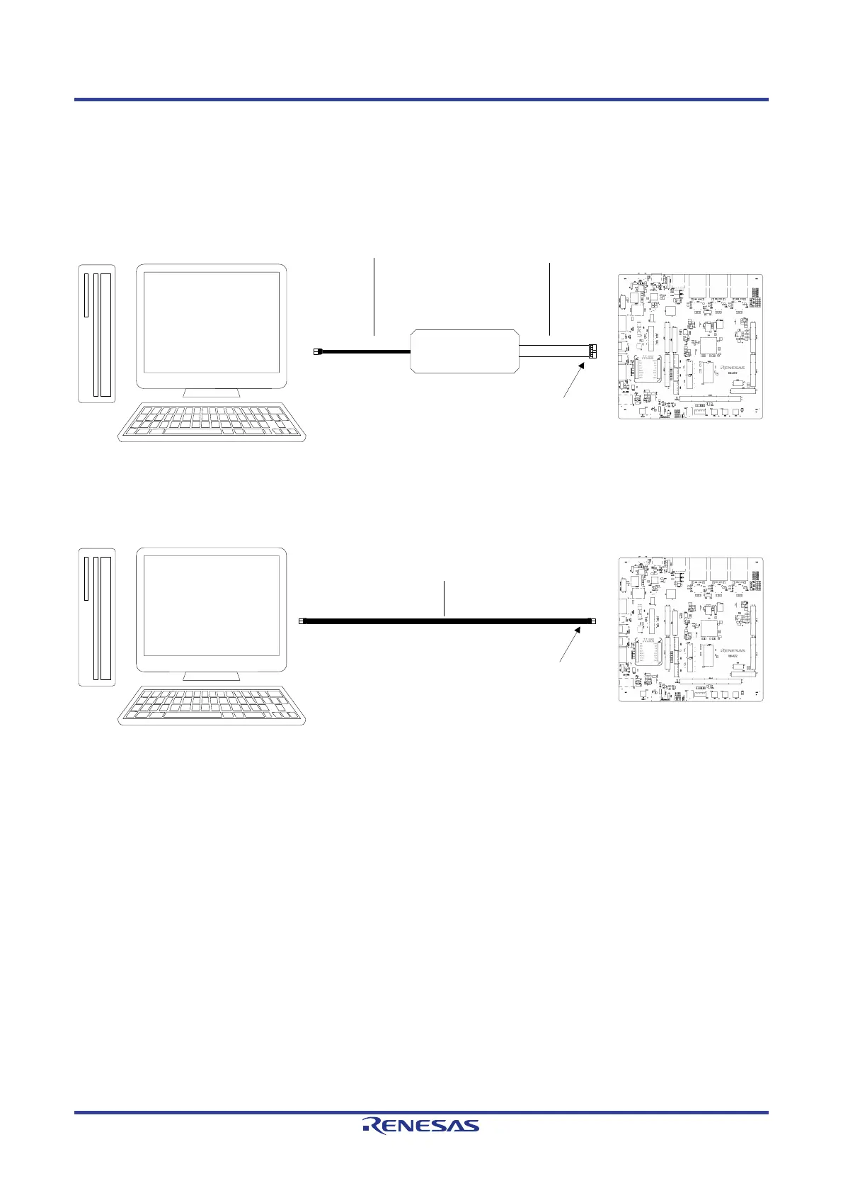
Figure 4-2 below shows the connection between the CPU board, emulator and the host PC, Figure 4-3
below shows the connection between the CPU board, J-Link
®
OB and the host PC.
HOST PC
Emulator
CPU Board
User Interface cable
USB cable
(Included in the debugger)
Connect to J13 or J20 or CN9
Figure 4-2: Emulator Connection Diagram (External Emulator)
HOST PC
USB cable (Type-A male to Micro male)
CPU Board
Connect to J10
Figure 4-3: Emulator Connection Diagram (J-Link
®
OB)
 Loading...


