Renesas Starter Kit+ for RZ/T2M 6. Configuration
R20UT4939EG0100 Rev. 1.00 Page 53 of 87
Apr 20, 2022
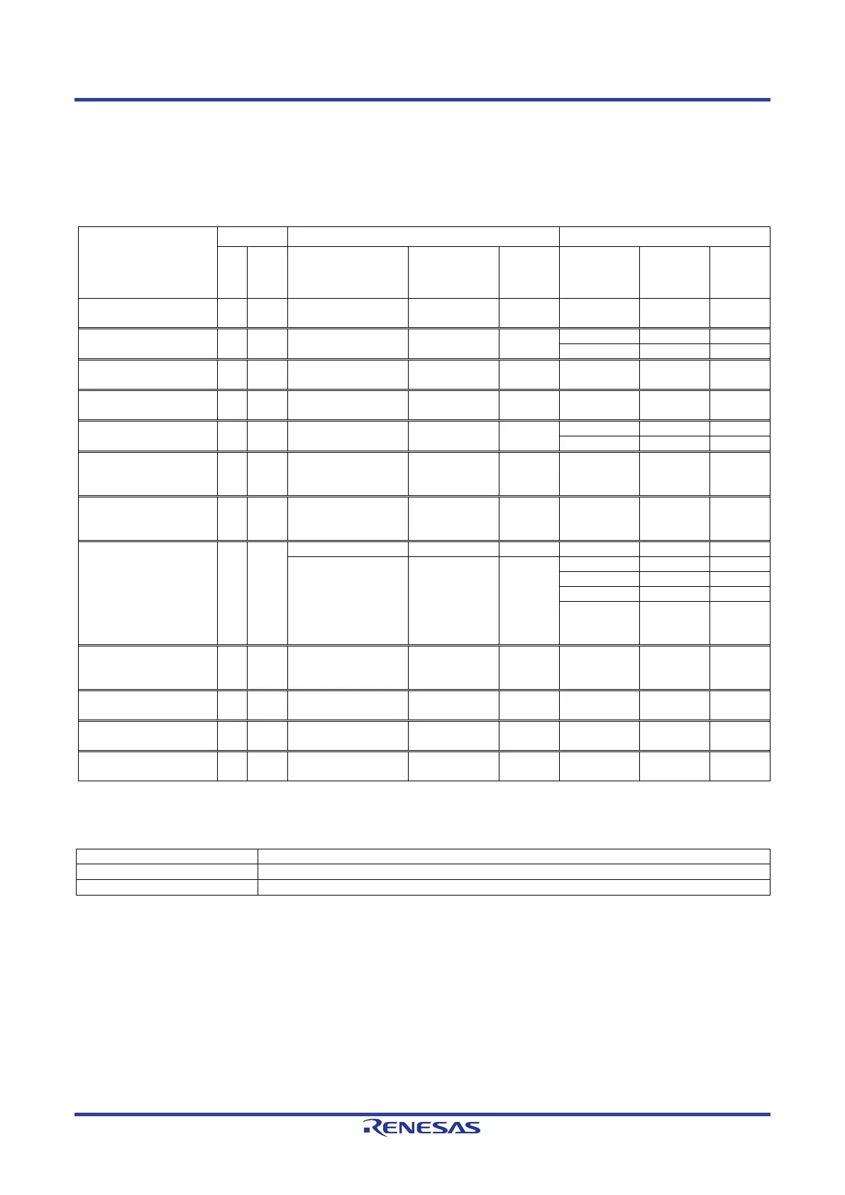
6.13 EtherCAT Slave Controller Configuration
Table 6-31, Table 6-32, Table 6-33, Table 6-41 below details the function of the option links associated with
EtherCAT Slave Controller (ESC) Configuration.
Table 6-41: ESC Configuration Option Links
Signal name
Pin
Port
Signal Fit DNF
Interface
/Function
Fit DNF
ETH_LED0_MDV1
(ESC_LEDRUN)
A10 P20_2 ETH_LED0_MDV1 - - ETH_LED0.A R6 -
ETH_LED1_MDV2
(ESC_LEDERR)
C9 P20_3 ETH_LED1_MDV2 - -
ETH_LED2_MDV0
(ESC_LINKACT0)
C11 P20_1 ETH_LED2_MDV0 - - ETH_LED2.A R8 -
ETH_LED3_MDV3
(ESC_LINKACT1)
B10 P20_4 ETH_LED3_MDV3 - - ETH_LED3.A R11 -
A9 P21_0 ETH_LED5 - -
(ESC_SYNC0,
R18 P13_6 M1_TRDCLK_33 IC42.8 - JA2-A.26 - -
(ESC_LATCH0,
N16 P13_5 M1_TRCCLK_33 IC42.9 - JA2-A.25 - -
ESC_RESETOUT# E10 P20_7
ESC_RESETOUT# - -
IC16.53
( 1-2 pin
-
ESC_B_RESETOUT# F7 P23_7 ESC_B_RESETOUT# - - IC16.53
( 2-3 pin
-
R11 P10_4 ETH0_LINK IC36.4 - IC35.59 - -
R1 P05_5 ETH1_LINK IC32.4 - IC31.59 - -
G5 P00_5 ETH2_LINK IC17.4 - IC16.59 - -
Table 6-42 below details the function of the switches associated with the ESC.
Table 6-42: ESC Configuration Switch Settings
Enable the external bus signal. *
1
Enables signals other than the external bus. (CAN, Emulator, I
2
C, etc.)
*
1
: BUS (SDRAM) and ESC port 2 cannot be used at the same time.
 Loading...


