Renesas Starter Kit+ for RZ/T2M 6. Configuration
R20UT4939EG0100 Rev. 1.00 Page 38 of 87
Apr 20, 2022
6.5 Power Supply Configuration
Table 6-13 below details the function of the option links associated with Power Supply Configuration.
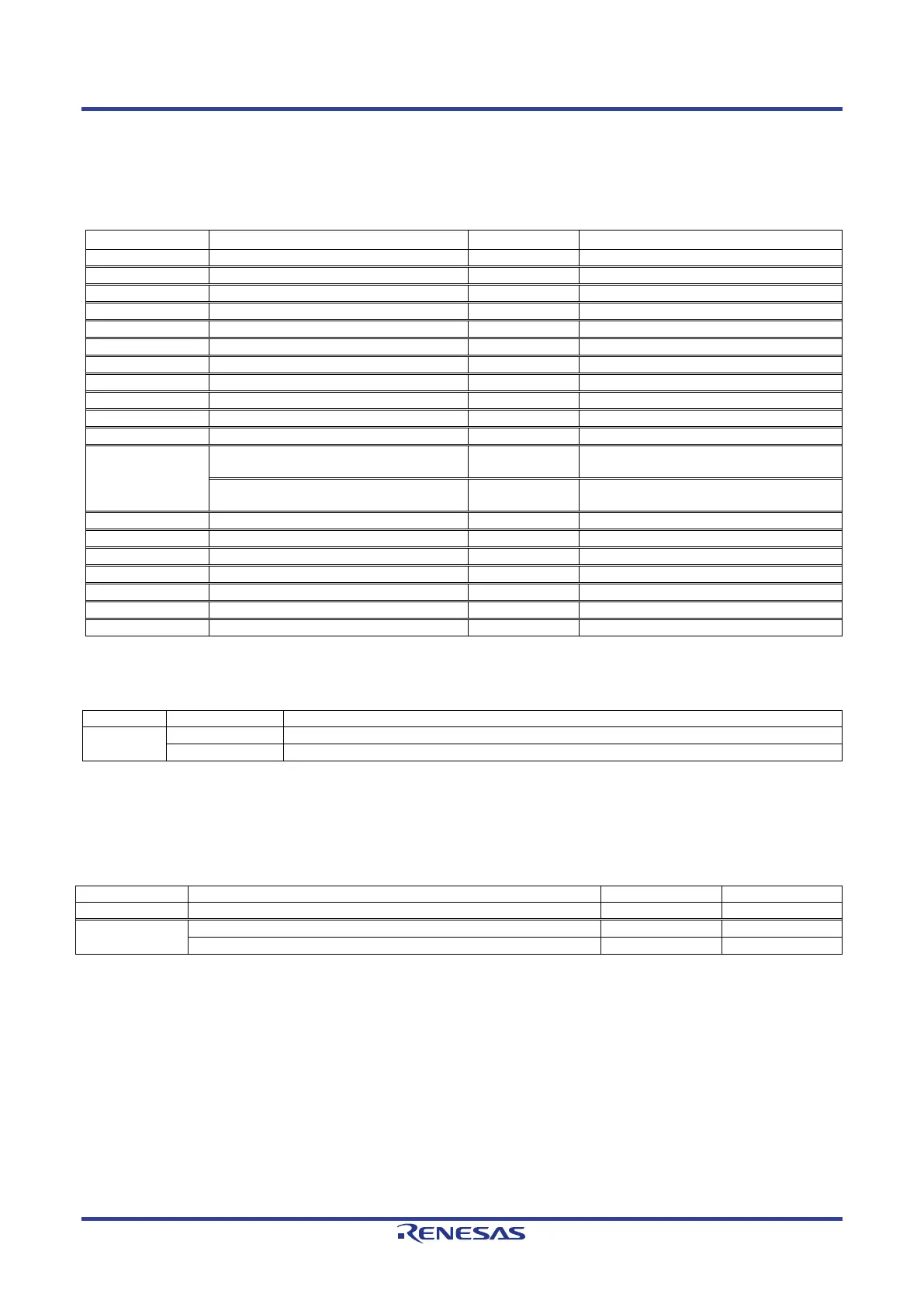
Table 6-13: Power Supply Configuration Option Links
Connect 5V Power rail to 5.0V.
Connect 5V Power rail to CON_5V.
Connect 3.3V Power rail to 3.3V.
Connect 3.3V Power rail to CON_3V3.
Connect 3.3V Power rail to +3V3JLOB.
Connect 1.8V Power rail to 1.8V.
Connect 1.1V Power rail to VCC11_RZCORE.
Connect 1.0V Power rail to ETH_VDD10.
Connect 2.5V Power rail to ETH_VDD25.
Connect 1.8V Power rail to VCC1833_0.
Connect 1.8V Power rail to VCC1833_1.
VCC1833_2
Connect 3.3V Power rail to VCC1833_2.
-
Connect 1.8V Power rail to VCC1833_2.
-
Connect 1.8V Power rail to VCC1833_3.
Connect 1.8V Power rail to VCC1833_4.
Connect 1.8V Power rail to VCC18_PLL0.
Connect 1.8V Power rail to VCC18_PLL1.
Connect 1.8V Power rail to VCC18_TSU.
Connect 1.8V Power rail to VCC18_ADC0.
Connect 1.8V Power rail to VCC18_ADC1.
Table 6-14 below details the function of the jumpers associated with the Power Supply.
Table 6-14: Power Supply Configuration Jumper Settings
CN17
Connect 3.3V Power rail to VCC1833_2. (When using SDRAM)
Connect 1.8V Power rail to VCC1833_2. (When using Ethernet port 2)
6.6 Clock Configuration
Table 6-15 below details the function of the option links associated with Clock Configuration.
Table 6-15: Clock Configuration Option Links
Connect 25MHz crystal (X3) to RZ/T2M.
EXTCLKIN
Connect 25MHz crystal (X1) via a clock generator (IC24) to RZ/T2M.
Connect JA2-A.2 to RZ/T2M.
 Loading...


