17
5.0 XCell
TM
C410v4B Controller Layout
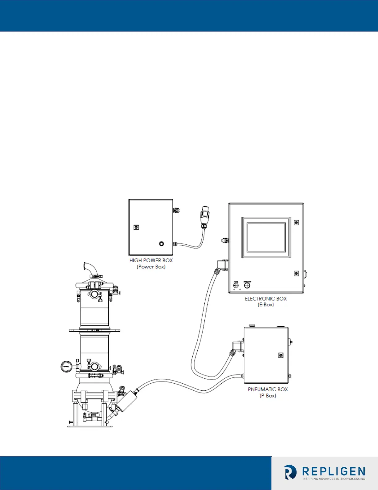
5.1 General Layout
The controller consists of three major components:
-P-Box
-E-Box
-Power-Box,
Figure 5a/b/c/d shows the details.
The E-Box and the P-Box interconnected with a cable that relays signal and power. A general
layout with the XCell™ ATF System is shown in Fig. 5a. the primary design objective is to
produce a modular system that will maximize adaptability of the system to the various space
requirements of the user’s facilities. One can envision the P-Box in proximity to the Filtration
Assembly, while the E-Box positioned distant to the Filtration Assembly, possibly mounted on
a wall or a skid. A stainless steel cart, specifically designed to house the three controller
components, and supporting components (vacuum pump, peristaltic pump and paperwork) is
available for purchase.
Figure 5a. XCell
TM
C410v4B General Arrangement
 Loading...


