22
6.0 C410v4B Controller Process and Control
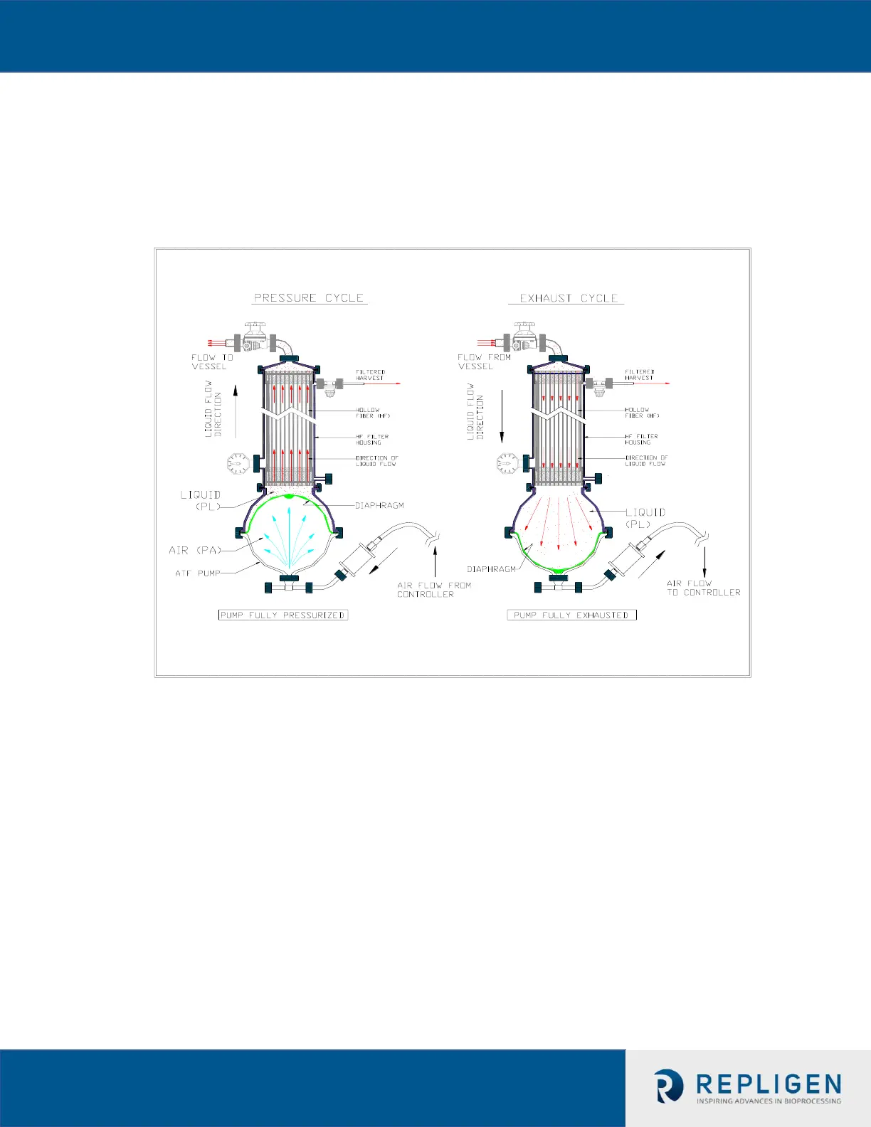
6.1 Control Overview
When the pressure cycle starts, the pressure to the diaphragm pump rapidly increases (as
measured by the P2 pressure sensor in the controller). At some critical pressure, the
diaphragm begins to move and the PA begins to expand. As the PA expands, P2 levels off
and must be sustained to maintain the expansion of the PA. This critical P2 pressure is also
known as the “Driving Pressure” or “Driving Force” (DP or DF).
Once the PA is fully inflated, the pressure within the pump chamber will begin to spike;
e.g. the diaphragm stops moving and begins to stretch. The controller takes advantage of
this spike by using a cycle Switch Offset (SO) to indicate when to switch to the Exhaust
cycle. Similar mechanism applies to the Exhaust cycle.
To assure optimum results with the XCell™ ATF System, one should keep in mind the following
two general rules:
1. The diaphragm motion must be a continuous one between the Pressure cycle and the
Exhaust cycle and vice versa (i.e. no dwell time)
2. Ideally, the stroke travel of the diaphragm must be reversibly between fully Pressurized
and fully Exhausted extremes
Note: There should be no dwell time for the diaphragm at any point of the cycle.
 Loading...


