3
1.1 XCell
TM
ATF System Pump Cycle
The Diaphragm Pump is the heart of the XCell™ ATF System process. It produces an
alternating flow through the HFM (lumen side) or SM. The XCell™ ATF System provides a
pulsating, reversible, flow of liquid, back and forth, between the process vessel and the
Diaphragm Pump. The following is a description of that process:
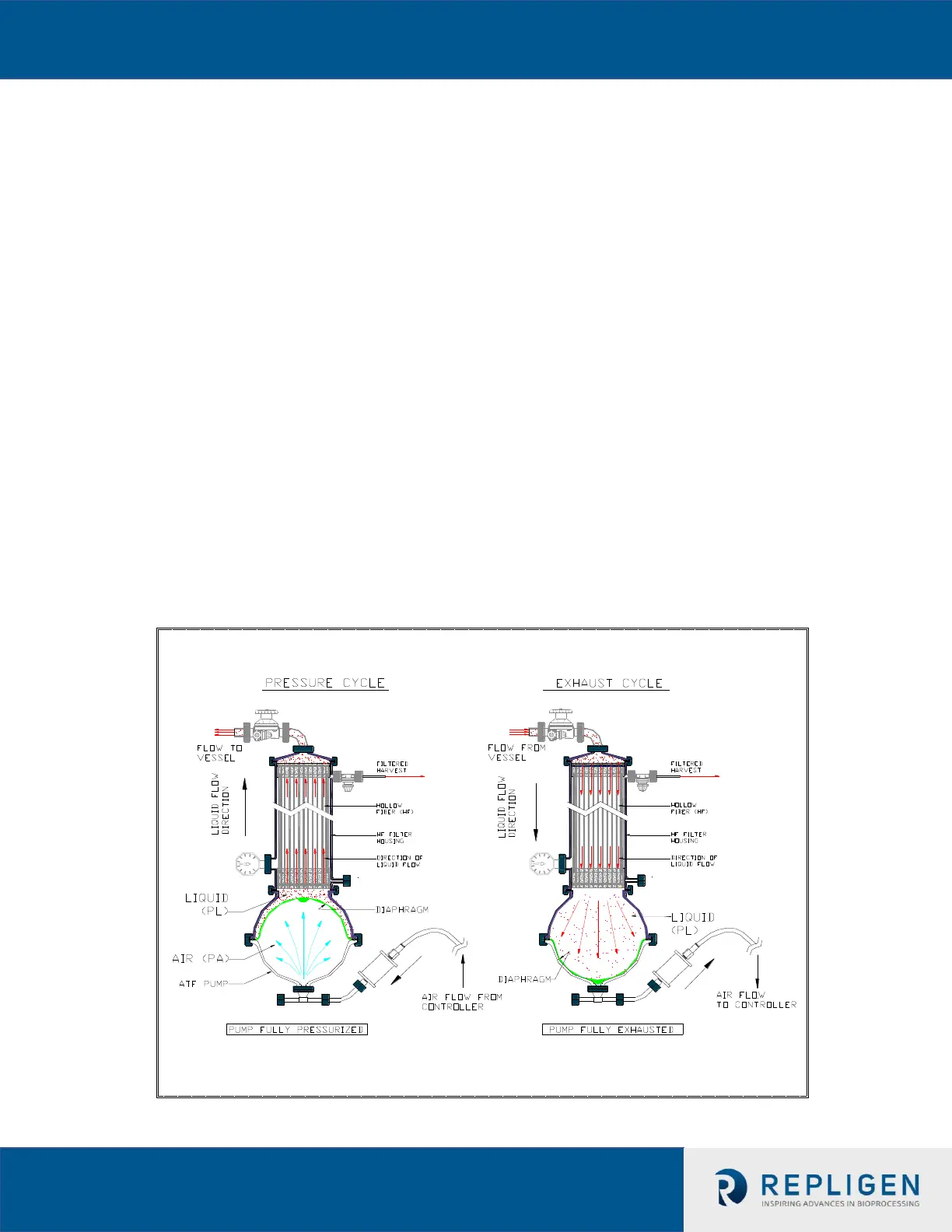
The Diaphragm Pump is partitioned into two chambers with a flexible diaphragm, Figure
2. One of the pump chambers, the Pump Liquid (PL) chamber is connected to the Filter
Housing, which, in turn, is connected to the process vessel. Therefore, any flow between
the Diaphragm Pump and process vessel will be through the filtration device. The second
pump chamber, the Pump Air (PA) chamber, is connected to the pump flow control
system. Typically, controlled addition of compressed air into the PA chamber increases
the pressure in the chamber relative to the process vessel, forcing the flexible diaphragm
partitioning the two chambers to move into the PL chamber and towards the vessel.
Liquid in the PL chamber is forced through the filter to the process vessel. The flow
through the HFM (lumen side) generates tangential flow in one direction. This pumping
phase (or cycle) in the direction of the bioreactor is called the Pressure Cycle. Inversely,
with a pressurized process vessel relative to PA or PL, or with an external vacuum supply,
liquid will flow in the reverse direction, from process vessel, through the HFM (lumen
side), to the PL chamber, generating tangential flow in the other direction. This pumping
phase (or cycle) in the direction of the XCell™ ATF pump is called the Exhaust Cycle. These
alternating pump cycles are then repeated continuously. See Figure 2.
Figure 2. XCell™ ATF System Pump Cycles
 Loading...


