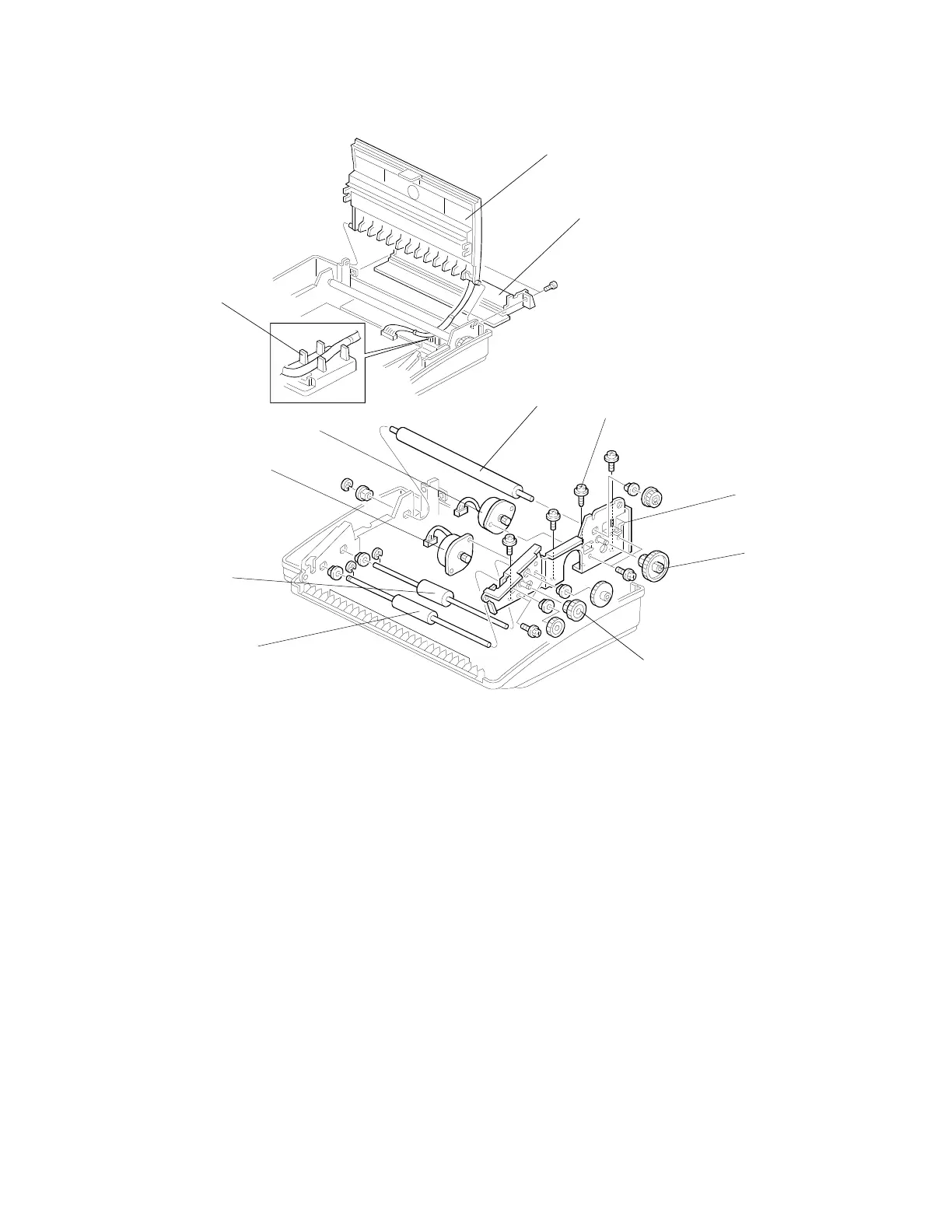
5.5. ROLLERS AND MOTORS
[A]
[B]
[L]
H068R010.wmf
[J]
[K]
[C]
[I]
[H]
[G]
[E]
[D]
H068R009.wmf
First, remove the upper cover, scanner roller, CIS, and the cutter ass’y.
[A]: Rear Cover (2 screws)
[B]: Printer Cover (1 connector)
[C]: Right side plate (4 screws)
[D]: Rx Motor (2 screws, 1 connector)
[E]: Tx Motor (2 screws, 1 connector)
[F]: Idle Gear
[G]: Feed Roller (1 gear, 2 bushings, 1 E-ring)
[H]: R1 Roller (1 gear, 2 bushings, 1 E-ring)
[I]: Idle Gear
[J]: Platen Roller (1 gear, 2 bushings, 1 E-ring)
NOTE:
1. When installing the right side plate, the screw [K] should be a tapping screw.
2. When installing the printer cover, the harness of the thermal head should be
routed between tabs [L]. Otherwise, the machine may not work correctly.
REPLACEMENT AND ADJUSTMENT August 7th, 1995
{<2nd Lev Title]
5-6
 Loading...