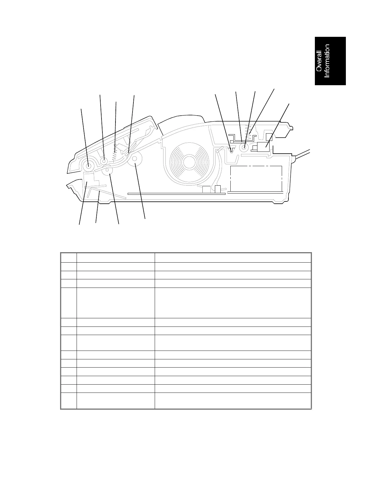
1.3. COMPONENT LAYOUT
1.3.1. Mechanical Components
No. Name Description
1
ADF Roller Picks up pages of the document.
2
R1 Roller Feeds the document through the scanner.
3
CIS Spring This applies pressure against the scanner roller.
4
Contact Image Sensor
(CIS) Assembly
This sensor reads and converts the light reflected from
the document into an analog video signal. An LED
array, which illuminates the document, is contained in
this unit.
5
Scanner Roller Feeds the document through the scanner.
6
Document Feed Roller Feeds the document through the scanner.
7
Separation Pad Spring This applies pressure to prevent the ADF roller from
feeding more than one sheet at a time.
8
Separation Pad Allows one page into the scanner.
9
Decurler This applies stress to the paper to remove the curl.
10
Thermal Head This prints by applying heat to the thermal paper.
11
Platen Roller This feeds printouts out of the machine.
12
Thermal Head Spring This applies pressure against the platen roller.
13
Cutter Assembly This consists of the cutter sensor, paper guide frame,
rotary cutter blade, cutter motor, and printer jam sensor.
1
2
6
8
3
4
5
7
9
10
11
12
13
H068D001.wmf
August 7th, 1995 OVERALL MACHINE INFORMATION
COMPONENT LAYOUT
1-5
 Loading...