1. Rear cover
Open to access the inside of the printer.
Open here to replace the fusing unit.
2. Power connector
Connect the power cord to the printer. Insert the other end into an electrical outlet.
3. USB port A
Connect external devices such as a card authentication device, etc.
4. USB port B
Connect to the USB port of the USB device server. Remove the cover to use this port.
5. Ethernet port
Use a network interface cable to connect the printer to a network.
6. Optional interface board slot
Optional interface boards can be inserted.
Insert an optional wireless LAN interface board, IEEE 1284 interface board, USB device server, or Extended
USB Board.
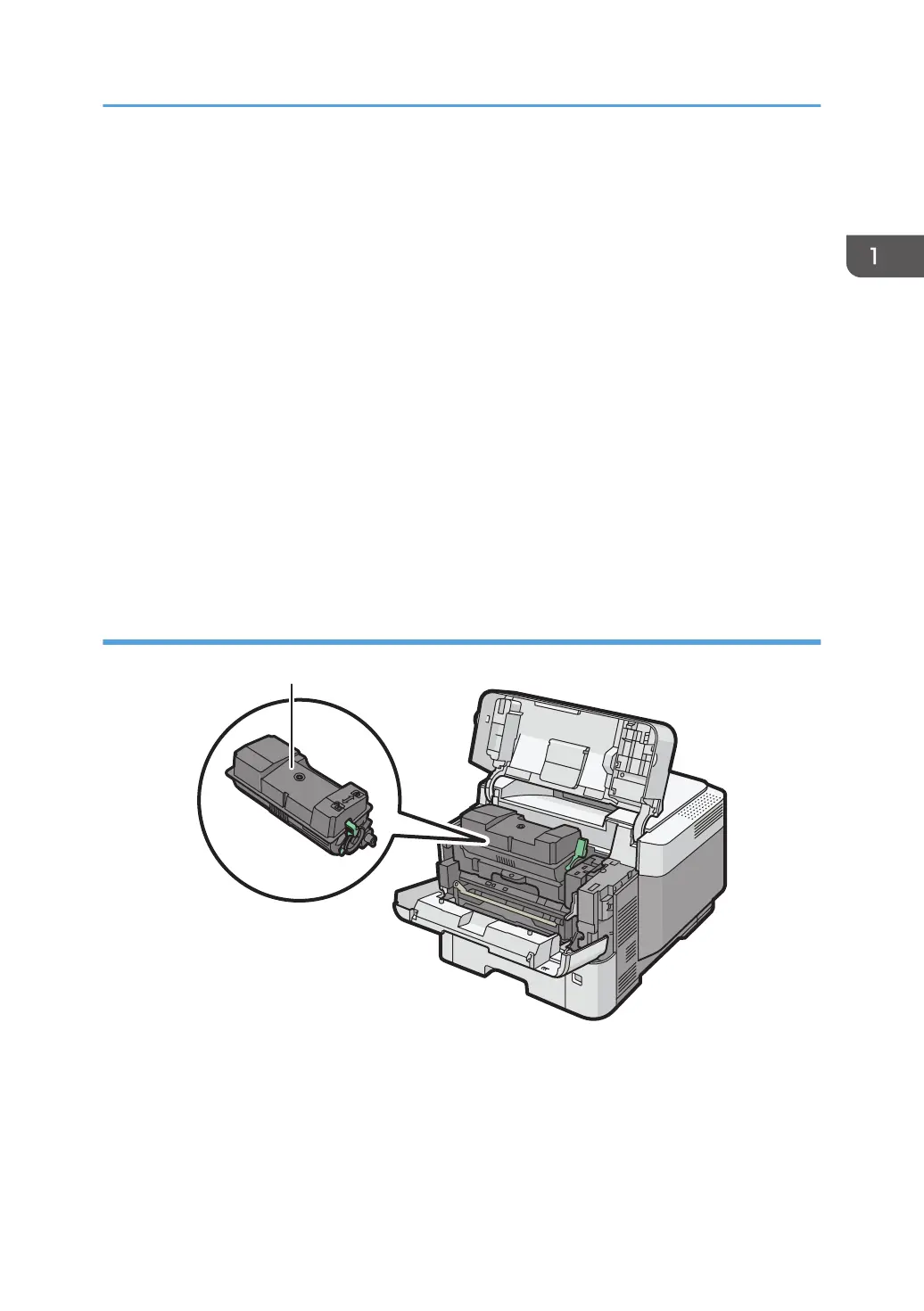
Interior: Front view
1. Print cartridge
Messages appear on the screen when the print cartridge needs to be replaced, or a new cartridge needs to
be prepared.
For details about the messages that appear on the screen when consumables need to be replaced, see
page 32 "Replenishing and Replacing Consumables".
Guide to Names and Functions of Components
11
 Loading...