f
c
≥50 MHz, input signal level = -20 dBm, attenuation = 0 dB, preamp off.
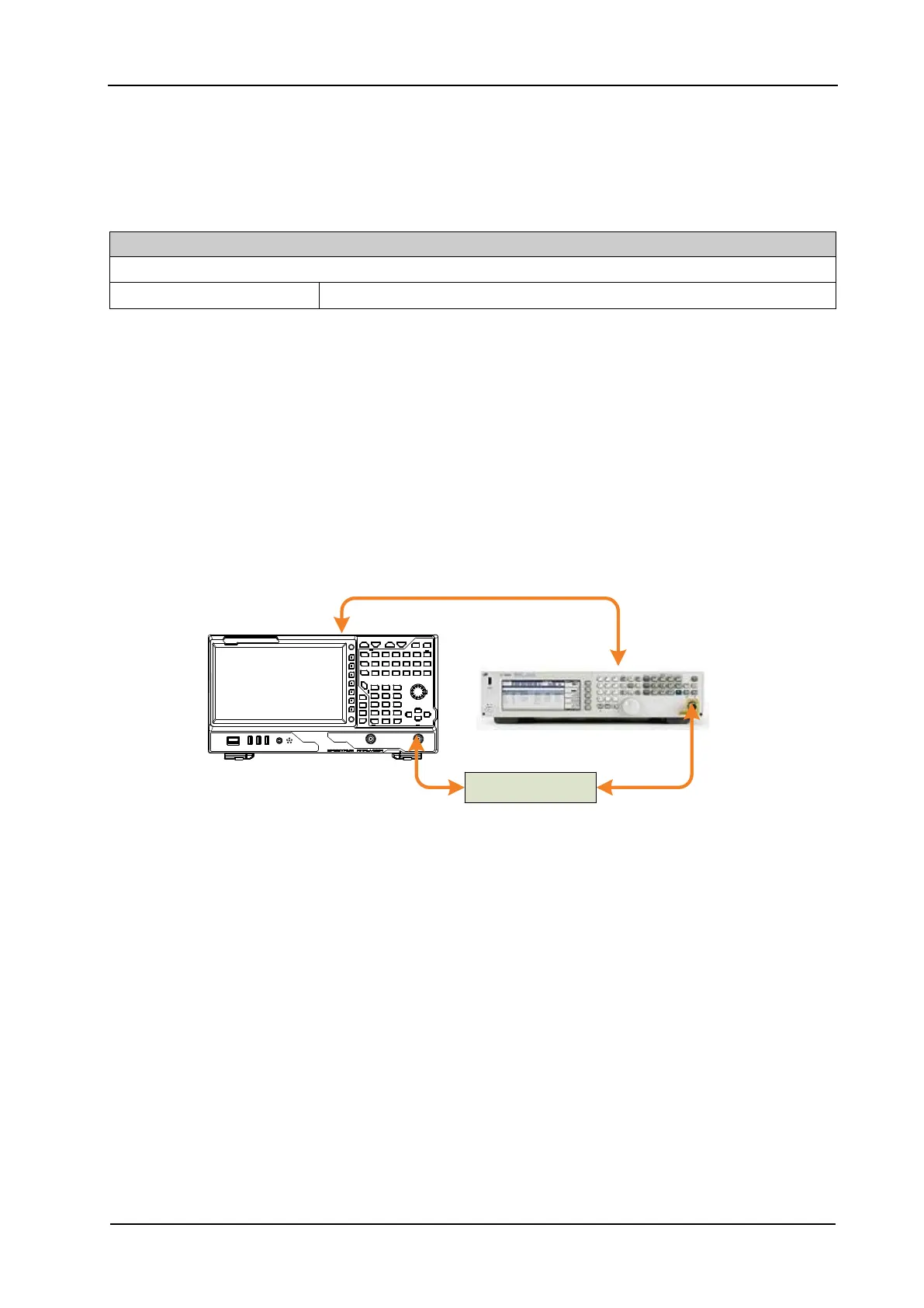
Figure 2-5 Second Harmonic Distortion Test Connection Diagram
Test Procedures
1. Synchronize the signal generator and spectrum analyzer. Connect the output terminal of the
signal generator with the 300 MHz low-pass filter. Then connect the filter with the RF input
terminal of the spectrum analyzer.
2. Set the output frequency of the signal generator to 300 MHz; set the amplitude to -20 dBm.
3. Configure the spectrum analyzer:
a) Set the center frequency to 300 MHz.
b) Set the span to 10 kHz.
c) Set the maximum mixer level to -20 dBm.
d) Set the reference level to -10 dBm.
 Loading...