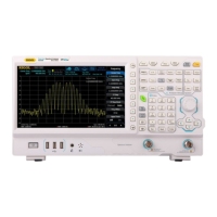
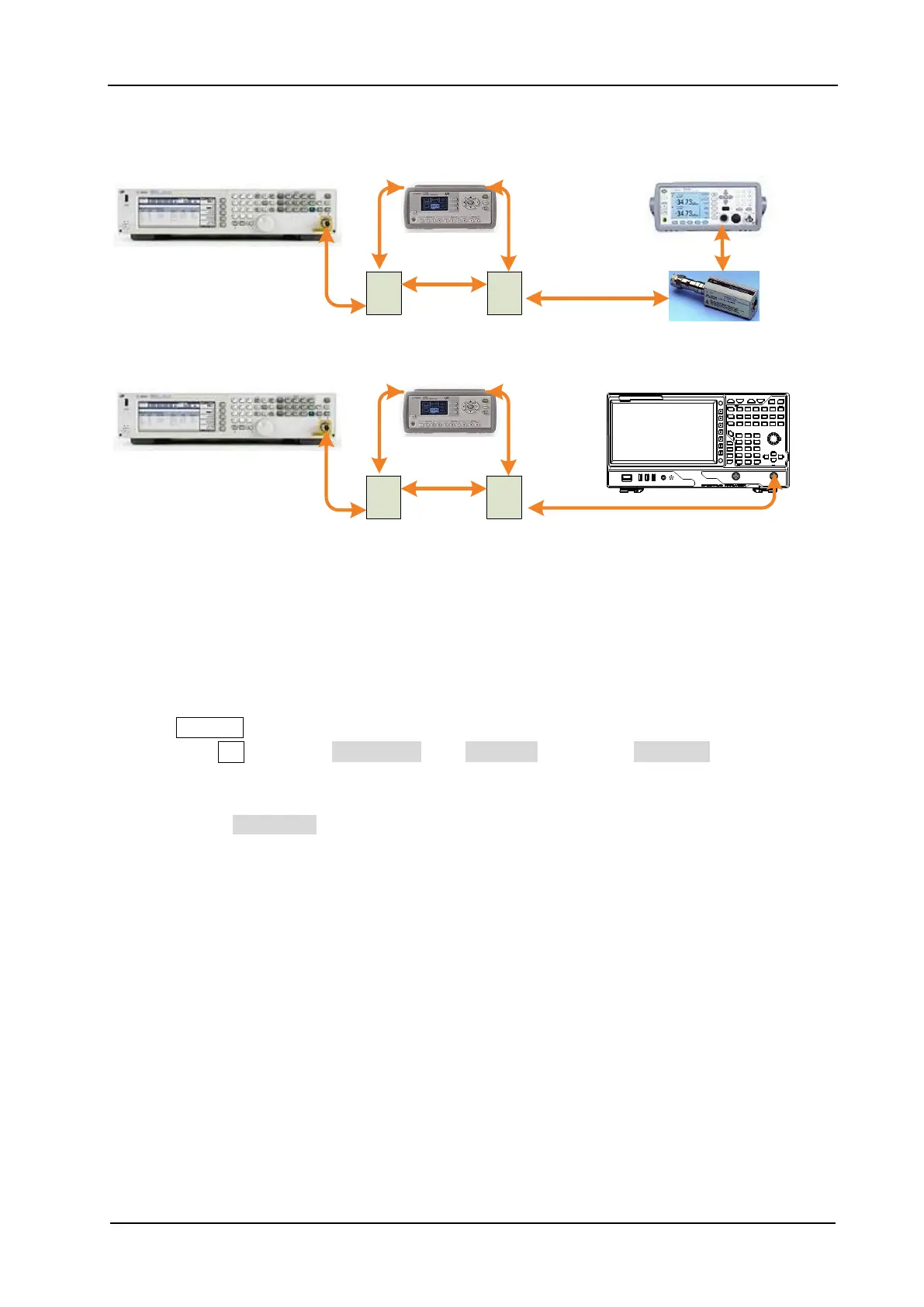
Figure 2-8 Input Attenuation Switching Uncertainty Test Connection Diagram
Test Procedures
1. Calibrate the power meter:
a) Connect the power sensor with the [REF] terminal and Channel A of the power meter. Press
Channel and set the frequency of Channel A to 50 MHz.
b) Press Cal and enable Power Ref in the Zero/Cal menu. Press Zero+Cal and wait for the
calibration to finish; then, observe whether the measurement value of the power meter is a
0 dBm, 50 MHz signal.
c) Disable Power Ref.
2. Connect the output terminal of the signal generator with the program-controlled attenuator;
then, connect the program-controlled attenuator with the power sensor, as shown in Figure 2-8
(a).
3. Set the output frequency of the signal generator to 50 MHz; set the amplitude to +10 dBm.
4. Set the attenuation of the program-controlled attenuator to 20 dB and measure the amplitude
with the power meter. Use the formula below to calculate the system error reference value.
System Error Reference Value = Power Meter Measurement Value - (+10 dBm – 20
dB). Record the calculation result in the test record form.
5. Modify the attenuation of the program-controlled attenuator according to the Test Record
Form (keep other parameters unchanged). Each time the attenuation is modified, measure the
 Loading...